


Appendix A: Special Device List
390
FX3G Series Programmable Controllers
User's Manual - Hardware Edition
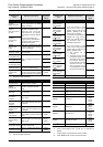
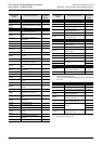
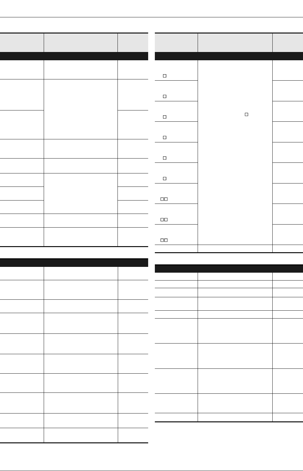
Appendix A-1 Special Auxiliary Relay (M8000 to M8511)
*1. Executed at END instruction
*2. Cleared when PLC switches from RUN to STOP.
*3. Executed at END instruction.
*4. Cleared when PLC switches from RUN to STOP.
*5. Cleared when PLC power supply from OFF to ON.
*6. Serial communication error 2 [ch2] PLC is detected by
M8438.
*7. Cleared when PLC switches from STOP to RUN.
*8. When M8069 is ON, I/O bus check is executed.
Number and
name
Operation and function
Correspond-
ing special
device
PLC Mode
M 8030
*1
Battery LED OFF
When M8030 set to ON, LED on
PLC is not lit even if low battery
voltage is detected.
-
M 8031
*1
Non-latch memory
all clear
If this special auxiliary relay is
activated, the ON/OFF image
memory of Y, M, S, T, and C, and
present values of T, C, D, special
data registers and R are cleared to
zero.
However, file registers (D) in
program memory, and extension
file registers (ER) in the memory
cassette are not cleared.
-
M 8032
*1
Latch memory
all clear
-
M 8033
Memory hold
STOP
When PLC is switched from RUN
to STOP, image memory and data
memory are retained.
-
M 8034
*1
All outputs disable
All external output contacts of PLC
are turned OFF.
-
M 8035
Forced RUN mode
Refer to Programming Manual for
details.
-
M 8036
Forced RUN signal
-
M 8037
Forced STOP signal
-
[M]8038
Parameter setting
Communication parameter setting
flag (for N:N network setting)
D8176 to
D8180
M 8039
Constant scan
mode
When M8039 is ON, PLC waits
until scan time specified in D8039
and then executes cyclic operation.
D8039
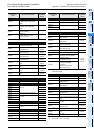
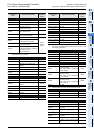
Step Ladder and Annunciator
M 8040
Transfer disable
While M8040 is turned ON, transfer
between states is disabled.
-
[M]8041
*2
Transfer start
Transfer from initial state is
enabled in automatic operation
mode.
-
[M]8042
Start pulse
Pulse output is given in response
to a start input.
-
M 8043
*2
Zero return
complete
Set this in the last state of zero
return mode.
-
M 8044
*2
Zero point
condition
Set this when machine zero return
is detected.
-
M 8045
All output reset
disable
Disables the 'all output reset'
function when the operation mode
is changed.
-
[M]8046
*3
STL state ON
ON when M8047 is ON and either
of S0 to S899 or S1000 to S4095 is
active.
M8047
M 8047
*3
STL monitoring
enable
D8040 to D8047 are enabled when
M8047 is ON.
D8040 to
D8047
[M]8048
*3
Annunciator operate
ON when M8049 is ON and either
of S900 to S999 is ON.
-
M 8049
*2
Annunciator enable
D8049 is enabled when M8049 is
ON.
D8049
M8048
Number and
name
Operation and function
Correspond-
ing special
device
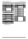
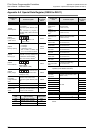
Interrupt Disable
M8050
(Input interrupt)
I00 disable
*4
• If an input interrupt or timer
interrupt occurs while a special
auxiliary relay for that interrupt
(M8050 - M8058) is ON, the
interrupt will not operate.
For example, turning M8050 ON
disables the I00 interrupt;
hence, the interrupt routine is
not processed even in an
allowable program area.
• If an input interrupt or timer
interrupt occurs while a special
auxiliary relay for that interrupt
(M8050 - M8058) is OFF,
a) The interrupt will be
accepted.
b) The interrupt routine will be
processed promptly if it is
permitted by the EI (FNC
04) instruction. However, if
the DI (FNC 05) instruction
disables interrupts, the
interrupt program will not
be processed until EI (FNC
04) permits the interrupts.
-
M8051
(Input interrupt)
I10 disable
*4
-
M8052
(Input interrupt)
I20 disable
*4
-
M8053
(Input interrupt)
I30 disable
*4
-
M8054
(Input interrupt)
I40 disable
*4
-
M8055
(Input interrupt)
I50 disable
*4
-
M8056
(Timer interrupt)
I6 disable
*4
-
M8057
(Timer interrupt)
I7 disable
*4
-
M8058
(Timer interrupt)
I8 disable
*4
-
M 8059 Not used -
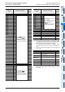
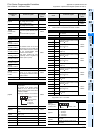
Error Detection
[M]8060 I/O configuration error D8060
[M]8061 PLC hardware error D8061
[M]8062
*5
Serial communication error [ch0] D8062
[M]8063
*5*6
Serial communication error 1
[ch1]
D8063
[M]8064 Parameter error D8064
[M]8065 Syntax error
D8065
D8069
D8314
D8315
[M]8066 Ladder error
D8066
D8069
D8314
D8315
[M]8067
*7
Operation error
D8067
D8069
D8314
D8315
M 8068 Operation error latch
D8068
D8312
D8313
M 8069
*8
I/O bus check -