


19 Display Module (FX3G-5DM)
309
FX
3G
Series Programmable Controllers
User's Manual - Hardware Edition
11
High-Speed
Counters
12
Output Wiring
13
Wiring for
Various Uses
14
Test Run,
Maintenance,
Troubleshooting
15
Input/Output
Powered
Extension Units
16
Input/Output
Extension
Blocks
17
Extension
Power Supply
Unit
18
Other Extension
Units and
Options
19
Display Module
20
Terminal Block
19.2 Installation and Removal
19.2 Installation and Removal
Be sure that the power is OFF when installing the display module.
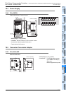
19.2.1 Installation
(when the expansion board/connector conversion adapter is not used together)
The FX3G-40MT/ES is used as the main unit in this example.
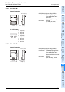
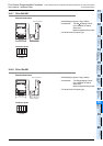
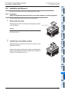
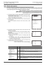
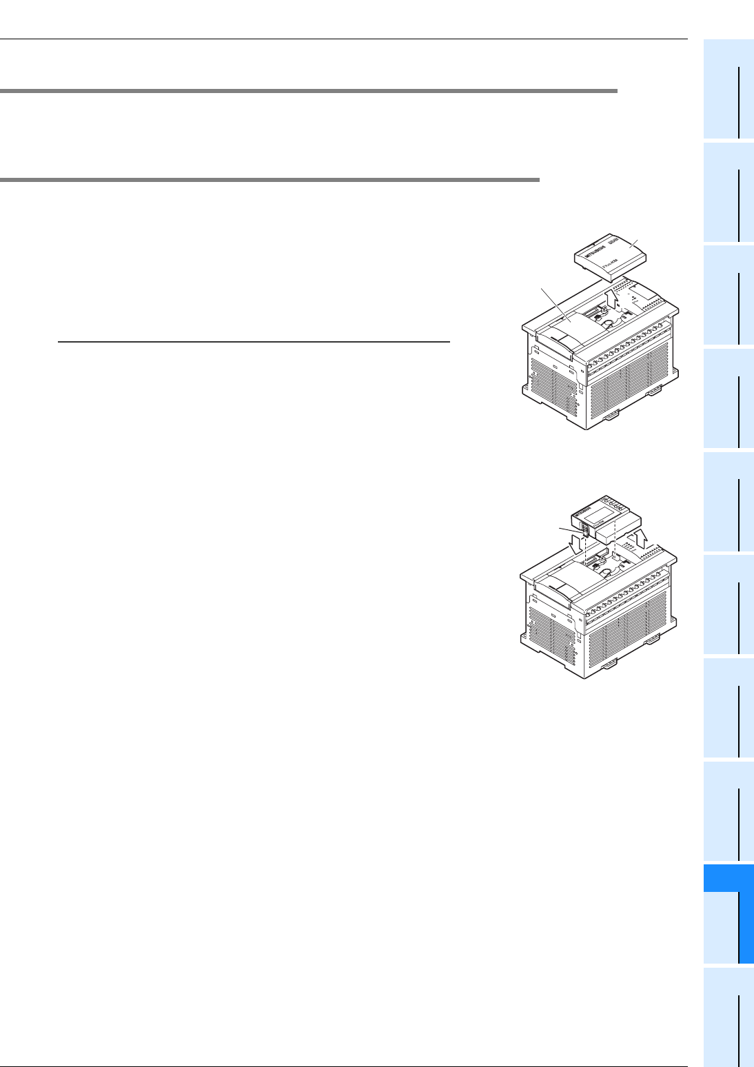
1 Remove the top cover.
Remove the top cover (A in the figure on the right) as shown
in the right figure.
Caution:
Display module cannot attach in the top cover (S) side of a 40/60-
point types main unit.
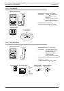
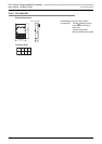
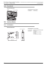
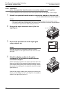
2 Install/remove the display module.
Attach the display module to the main unit as shown in the
right figure (arrow 2).
Remove the display module while pressing and holding the
display module fixing hook (B in the figure on the right) as
shown in the right figure (arrow 2').
A
1
Top cover (S)
2
B
2'