


9 Preparation for Wiring and Power Supply Wiring Procedures
9.4 Examples of External Wiring [AC Power Supply Type]
132
FX3G Series Programmable Controllers
User's Manual - Hardware Edition
9.4 Examples of External Wiring [AC Power Supply Type]
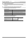
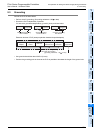
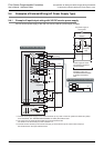
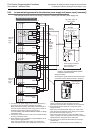
9.4.1 Example of input/output wiring with 24V DC service power supply
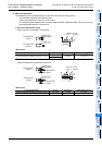
24V DC service power supply of the main unit can be used as a power supply for loads.
Power supply for loads
connected to sequencer
output terminals
As for the details of
emergency stop, see
"DESIGN PRECAUTIONS"
at "Safety Precautions"
field.
Class D
grounding
X0
S/S
0V
24V
Main unit
N
L
X1
5V 0V 24V
Input
impedance
X7
Fuse
Y0
COM0
Y2
Input extension block
S/S
*3
X0
COM2
AC power supply of
100 to 240V
PL
Power ON
Emergency
stop
MC
MC
MC MC
0V
24V
*1
S/S
0V
24V
24V
0V
Load
5V 0V 24V
*1
Connect the AC power supply to the L and N terminals (in any case of 100V AC system and 200V AC system).
As for the details, see "WIRING PRECAUTIONS" at "Safety Precautions" field.
*2
The "24V" and "0V" terminals are located on the output terminal side.
For details on the terminal layout, refer to Section 4.7.
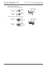
In the case of sink input wiring
In the case of source input wiring
Breaker
*2
*2
Connect the 24V terminal (in the case of sink input) or the 0V terminal (in the case of source input) to
the S/S terminal on the input extension block.
*3