


19 Display Module (FX3G-5DM)
317
FX
3G
Series Programmable Controllers
User's Manual - Hardware Edition
11
High-Speed
Counters
12
Output Wiring
13
Wiring for
Various Uses
14
Test Run,
Maintenance,
Troubleshooting
15
Input/Output
Powered
Extension Units
16
Input/Output
Extension
Blocks
17
Extension
Power Supply
Unit
18
Other Extension
Units and
Options
19
Display Module
20
Terminal Block
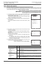
19.6 Monitor/Test Mode
19.6.3 Monitor screen and status display
→ Refer to Section 19.18 for the procedure used to display the current values as hexadecimal values.
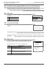
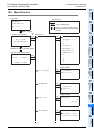
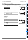
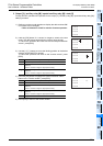
1. Data register [D (16-bit)] / extended register [R (16-bit)] / extended file register [ER (16-bit)]
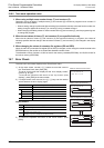
2. Data register [DD (32-bit)] / extended register [DR (32-bit)] / extended file register [DER (32-bit)]
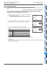
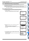
File register (D):
The file register (D) current value cannot be directly monitored at the
display module.
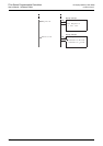
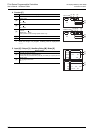
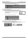
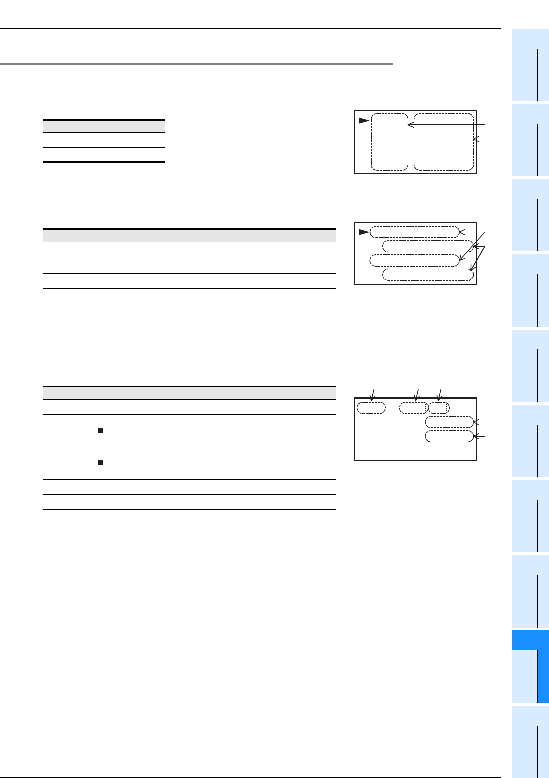
3. Timer [T]
*1. When not using it in a program, a setting value is displayed as
"-----".
Display Content
[1]
Device No.
[2]
Current value
Display Content
[1]
Device No.
[Upper 16-bit device No. (odd number)]
[Lower 16-bit device No. (even number)]
[2]
Current value
Display Content
[1]
Device No.
[2]
Contact image
ON:
OFF: Blank
[3]
Reset image
ON:
OFF: Blank
[4]
Current value
[5]
Setting value
*1
D0 0
D1 0
D2 0
D3 0
[2]
[1]
0
001
00
10
00
1
1
D1
0
D3
0
[2]
[1]
2
0
,
,
001
001
001
001
0
0
R
T0
001
[2] [3]
[4]
[5]
N
V
T
T
S
[1]
T