


19 Display Module (FX3G-5DM)
337
FX
3G
Series Programmable Controllers
User's Manual - Hardware Edition
11
High-Speed
Counters
12
Output Wiring
13
Wiring for
Various Uses
14
Test Run,
Maintenance,
Troubleshooting
15
Input/Output
Powered
Extension Units
16
Input/Output
Extension
Blocks
17
Extension
Power Supply
Unit
18
Other Extension
Units and
Options
19
Display Module
20
Terminal Block
19.14 Specified Device Monitor Function
19.14.2 Differences between specified device monitor screen and monitor/test screen
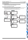
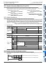
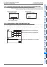
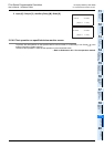
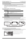
The figure below shows differences between the specified device monitor screen and the monitor/test screen.
→ Refer to Subsection 19.14.5 for a display example of the specified device monitor screen.
→ Refer to Subsection 19.6.3 for a display example of the monitor/test screen.
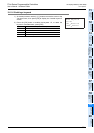
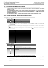
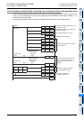
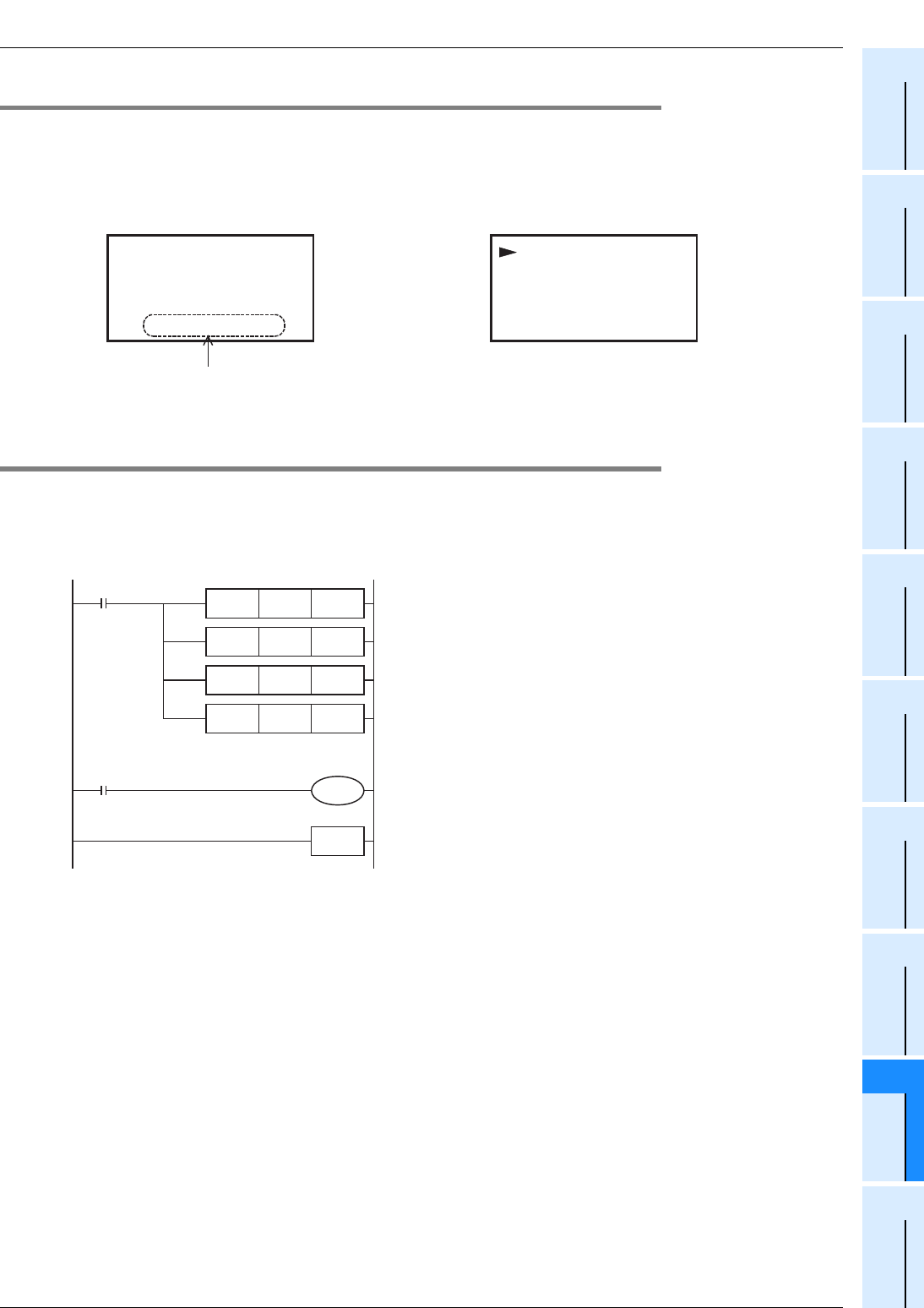
19.14.3 Program example1 (when monitoring/testing a timer)
In this program example, the device type to be displayed on the specified device monitor screen is set to
"timer (T)". Sets the device No. to "T10".
For testing the timer T10, turn ON M0 to enable the test operation.
In this program example, system information is assigned from D50 to D54 and from M50 to M64.
D100 3276
(Spec i f i ed)
70
D0
D1 0
D2 0
D3 0
0
001
00
10
00
1
1
32767
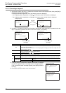
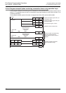
-Specified Device Monitor Screen
When D1000 is monitored
-Monitor/Test Screen
When D1000 is specified
In the case of a specified device monitor
screen "specified" is displayed.
Initial pulse
MOV K50 D8300
MOV K50 D8301
M8002
System information (system No.1) is set at D50 to D54.
System information (system No.2) is set at M50 to M64.
MOV K5 D50 Sets the device type to "Timer".
MOV K10 D51 Sets the device No. to "T10".
END
M0
When M0 turns ON, the test operation for T10 is enabled.
Test operation
enable command
M50