


11 Use of High-speed Counters
11.8 Examples of External Wiring (Rotary Encoder)
169
FX3G Series Programmable Controllers
User's Manual - Hardware Edition
11
High-Speed
Counters
12
Output Wiring
13
Wiring for
Various Uses
14
Test Run,
Maintenance,
Troubleshooting
15
Input/Output
Powered
Extension Units
16
Input/Output
Extension
Blocks
17
Extension
Power Supply
Unit
18
Other Extension
Units and
Options
19
Display Module
20
Terminal Block
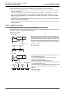
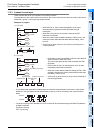
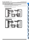
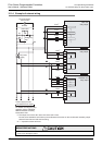
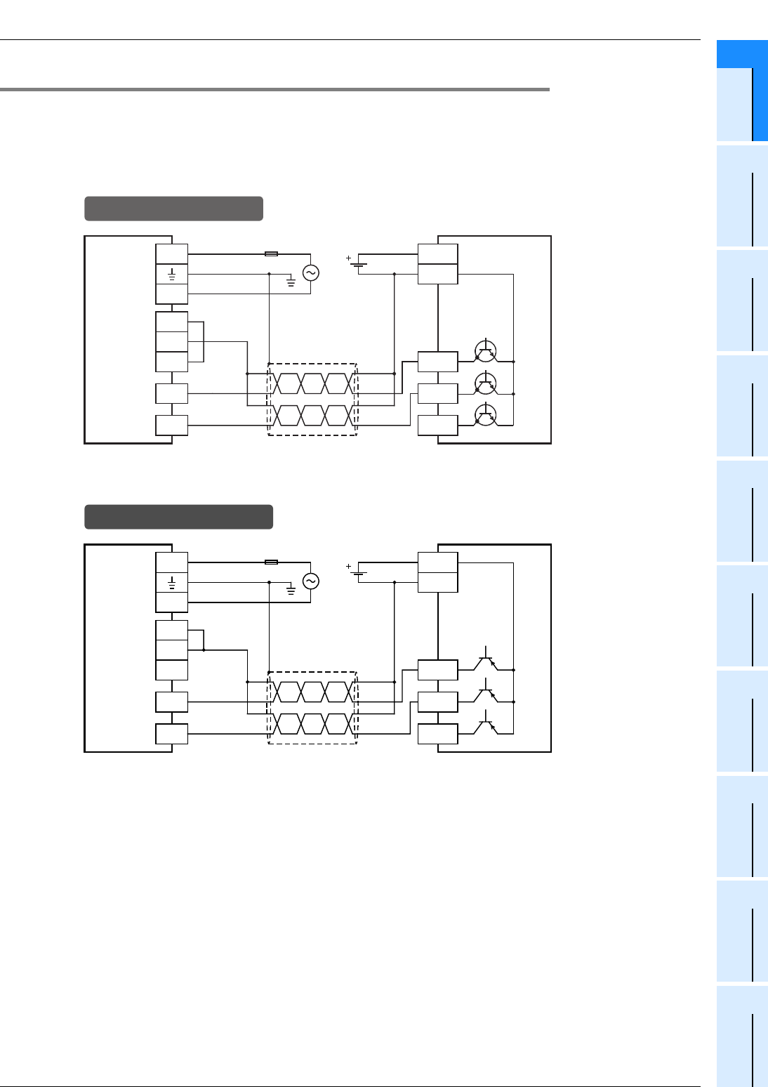
11.8.2 2-phase 2-input [C251 to C255]
The following examples of wiring apply to the cases where C251 is used. When another high-speed counter
number is used, wire the counter referring to the following diagrams.
It is recommended to use shielded twisted-pair cables for connection cables. Ground the shield of each
shielded cable only on the PLC side.
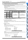
1) NPN open collector transistor output rotary encoder
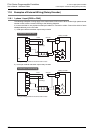
2) PNP open collector transistor output rotary encoder
* The grounding resistance should be 100Ω or less.
PLC
S/S
L
N
24V
0V
24V
Rotary encoder
Class D
grounding*
Fuse
24V DC
In the case of sink wiring
0V
X000
X001
Phase A
Phase B
Phase Z
* The grounding resistance should be 100Ω or less.
PLC
S/S
L
N
24V
0V
24V
Rotary encoder
24V DC
In the case of source wiring
0V
X000
X001
Phase A
Phase B
Phase Z
Class D
grounding*
Fuse