


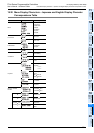
20 Terminal Block
353
FX3G Series Programmable Controllers
User's Manual - Hardware Edition
11
High-Speed
Counters
12
Output Wiring
13
Wiring for
Various Uses
14
Test Run,
Maintenance,
Troubleshooting
15
Input/Output
Powered
Extension Units
16
Input/Output
Extension
Blocks
17
Extension
Power Supply
Unit
18
Other Extension
Units and
Options
19
Display Module
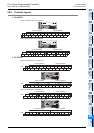
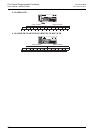
20
Terminal Block
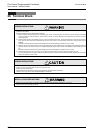
INSTALLATION PRECAUTIONS
• Use the product within the generic environment specifications described in section 4.1 of this manual.
Never use the product in areas with excessive dust, oily smoke, conductive dusts, corrosive gas (salt air, Cl2, H2S, SO2 or NO2),
flammable gas, vibration or impacts, or expose it to high temperature, condensation, or rain and wind.
If the product is used in such conditions, electric shock, fire, malfunctions, deterioration or damage may occur.
• Do not touch the conductive parts of the product directly.
Doing so may cause device failures or malfunctions.
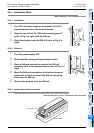
• Install the product securely using a DIN rail or mounting screws.
• Install the product on a flat surface.
If the mounting surface is rough, undue force will be applied to the PC board, thereby causing nonconformities.
• When drilling screw holes or wiring, make sure that cutting and wiring debris do not enter the ventilation slits.
Failure to do so may cause fire, equipment failures or malfunctions.
• Be sure to remove the dust proof sheet from the PLC's ventilation port when installation work is completed.
Failure to do so may cause fire, equipment failures or malfunctions.
• Connect the extension cables, peripheral device cables, input/output cables and battery connecting cable securely to their designated
connectors.
Loose connections may cause malfunctions.
• Turn off the power to the PLC before attaching or detaching the following devices.
Failure to do so may cause device failures or malfunctions.
- Peripheral devices, display modules, expansion boards and special adapters
- Extension units/blocks and FX Series terminal blocks
- Battery and memory cassette
WIRING PRECAUTIONS
• Make sure to cut off all phases of the power supply externally before attempting installation or wiring work.
Failure to do so may cause electric shock or damage to the product.
• Make sure to attach the terminal cover, offered as an accessory, before turning on the power or initiating operation after installation or
wiring work.
Failure to do so may cause electric shock.
WIRING PRECAUTIONS
• Connect the AC power supply to the dedicated terminals specified in this manual.
If an AC power supply is connected to a DC input/output terminal or DC power supply terminal, the PLC will burn out.
• Connect the DC power supply to the dedicated terminals specified in this manual.
If an AC power supply is connected to a DC input/output terminal or DC power supply terminal, the PLC will burn out.
• Do not wire vacant terminals externally.
Doing so may damage the product.
• When drilling screw holes or wiring, make sure cutting or wire debris does not enter the ventilation slits.
Failure to do so may cause fire, equipment failures or malfunctions.
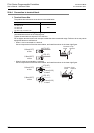
• Make sure to properly wire to the FX Series terminal blocks in accordance with the following precautions.
Failure to do so may cause electric shock, equipment failures, a short-circuit, wire breakage, malfunctions, or damage to the product.
- The disposal size of the cable end should follow the dimensions described in the manual.
- Tightening torque should follow the specifications in the manual.
- Tighten the screws using a Phillips-head screwdriver No.2 (shaft diameter 6mm (0.24") or less). Make sure that the screwdriver
does not touch the partition part of the terminal block.
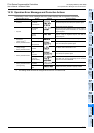
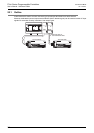
Terminal block DIN rail only
Main unit, FX2N Series I/O extension unit/block, FX2N/FX3U Series special
function block, and special adapter
DIN rail or direct mounting