


Teledyne API - Model 200EH/EM Operation Manual Operating Instructions
87
6.11.2. COM PORT DEFAULT SETTINGS
As received from the factory, the analyzer is set up to emulate a DCE or modem, with pin 3 of the DB-9
connector designated for receiving data and pin 2 designated for sending data.
COM1: RS-232 (fixed), DB-9 male connector.
o
Baud rate: 19200 bits per second (baud).
o
Data Bits: 8 data bits with 1 stop bit.
o
Parity: None.
COM2: RS-232 (configurable), DB-9 female connector.
o
Baud rate: 115000 bits per second (baud).
o
Data Bits: 8 data bits with 1 stop bit.
o
Parity: None.
CAUTION
Cables that appear to be compatible because of matching connectors may incorporate
internal wiring that make the link inoperable. Check cables acquired from sources other
than Teledyne Instruments for pin assignments before using.
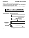
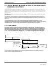
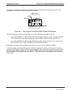
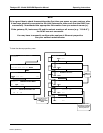
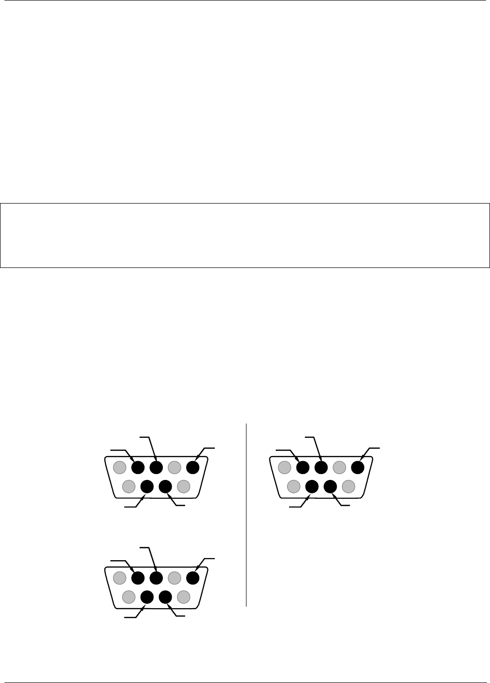
6.11.3. RS-232 COM PORT CABLE CONNECTIONS
In its default configuration, the M200EH/EM analyzer has two available RS-232 Com ports accessible via 2 DB-9
connectors on the back panel of the instrument. The COM1 connector is a male DB-9 connector and the COM2
is a female DB9 connector.
Male DB-9 (RS-232)
(As seen from outside analyzer)
(DTE mode)
(DCE mode)
1 2 3 4 5
6 7 8 9
RXD
GND
TXD
CTS
RTS
1 2 3 4 5
6 7 8 9
TXD
GND
RXD
RTS
CTS
Female DB-9 (COM2)
(As seen from outside analyzer)
(DTE mode)
1 234 5
6 789
RXD
GND
TXD
CTS
RTS
Figure 6-6-6: Back Panel connector Pin-Outs for COM1 & COM2 in RS-232 mode.
04521C (DCN5731)