


Teledyne API - Model 200EH/EM Operation Manual Operating Instructions
91
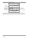
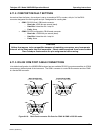
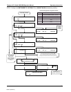
6.11.6. ETHERNET CARD CONFIGURATION
When equipped with the optional Ethernet interface, the analyzer can be connected to any standard 10BaseT
Ethernet network via low-cost network hubs, switches or routers. The interface operates as a standard TCP/IP
device on port 3000. This allows a remote computer to connect through the internet to the analyzer using
APICOM, terminal emulators or other programs.
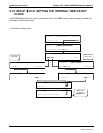
The firmware on board the Ethernet card automatically sets the communication modes and baud rate (115 200
kBaud ) for the
COM2 port. Once the Ethernet option is installed and activated, the COM2 submenu is replaced
by a new submenu,
INET. This submenu is used to manage and configure the Ethernet interface with your LAN
or Internet Server(s).
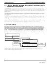
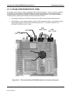
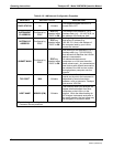
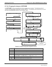
The card has four LEDs that are visible on the rear panel of the analyzer, indicating its current operating status.
Table 6-11: Ethernet Status Indicators
LED FUNCTION
LNK (green) ON when connection to the LAN is valid.
ACT (yellow) Flickers on any activity on the LAN.
TxD (green) Flickers when the RS-232 port is transmitting data.
RxD (yellow) Flickers when the RS-232 port is receiving data.
6.11.6.1. Ethernet Card COM2 Communication Modes and Baud Rate
The firmware on board the Ethernet card automatically sets the communication modes for the COM2 port. The
baud rate is also automatically set at 115 200 kBaud.
6.11.6.2. Configuring the Ethernet Interface Option using DHCP
The Ethernet option for you M200EH/EM uses Dynamic Host Configuration Protocol (DHCP) to automatically
configure its interface with your LAN. This requires your network servers also be running DHCP. The analyzer
will do this the first time you turn the instrument on after it has been physically connected to your network. Once
the instrument is connected and turned on it will appear as an active device on your network without any extra
set up steps or lengthy procedures.
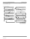
Should you need to, the Ethernet configuration properties are viewable via the analyzer’s front panel See Table
6-12.
04521C (DCN5731)