


Teledyne API - Model 200EH/EM Operation Manual Getting Started
15
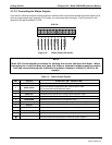
3.1.3. PNEUMATIC CONNECTIONS
NOTE
To prevent dust from getting into the analyzer, it was shipped with small plugs inserted
into each of the pneumatic fittings on the rear panel. Make sure that all dust plugs are
removed before attaching exhaust and supply gas lines.
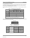
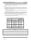
Table 3-5: Inlet / Outlet Connector Nomenclature
REAR PANEL LABEL FUNCTION
SAMPLE
Connects the sample gas to the analyzer. When operating the analyzer
without zero span option, this is also the inlet for any calibration gases.
EXHAUST
Connects the exhaust of the analyzer with the external vacuum pump.
SPAN
On Units with zero/span valve or IZS option installed, this port connects the
external calibration gas to the analyzer.
ZERO AIR
On Units with zero/span valve or IZS option installed, this port connects the
zero air gas or the zero air cartridge to the analyzer.
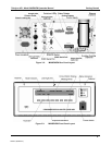
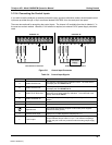
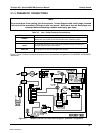
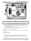
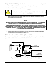
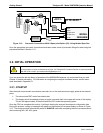
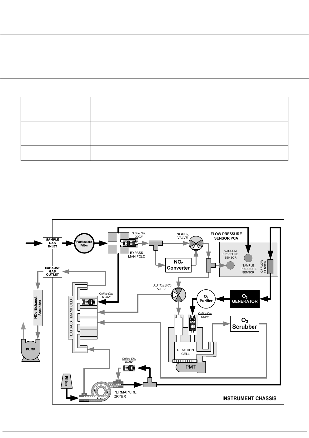
Figure 3-7 and 3.8 show the internal pneumatic flow of the standard configuration of the M200EH and M200EM
respectively.
Figure 3-7: M200EH Internal Pneumatic Block Diagram - Standard Configuration
04521C (DCN5731)