


Theory of Operation Teledyne API - Model 200EH/EM Operation Manual
212
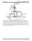
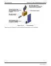
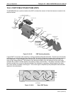
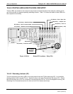
10.4.3. PHOTO MULTIPLIER TUBE (PMT)
The M200EH/EM uses a photo multiplier tube (PMT) to detect the amount of chemiluminescence created in the
sample chamber.
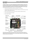
PMT Housing End Plate
This is the entry to the PMT Exchange
PMT Preamp PCA
High voltage Power Supply
(HVPS)
PMT
PMT Cold Block
Connector to PMT
Pre Amp PCA
12V Power
Connector
Cooling Fan
Housing
TEC Driver PCA
PMT Heat Exchange Fins
Li
g
ht from Reaction
Chamber shines
throu
g
h hole in side
of Cold Block
Insulation Gasket
PMT Power Supply
& Aux. Signal
Connector
PMT Output
Connector
Thermo-Electric Cooler
(TEC)
PMT Temperature
Senso
r
O-Test LED
Figure 10-10-18: PMT Housing Assembly
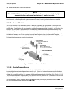
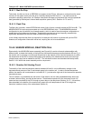
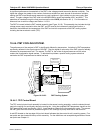
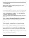
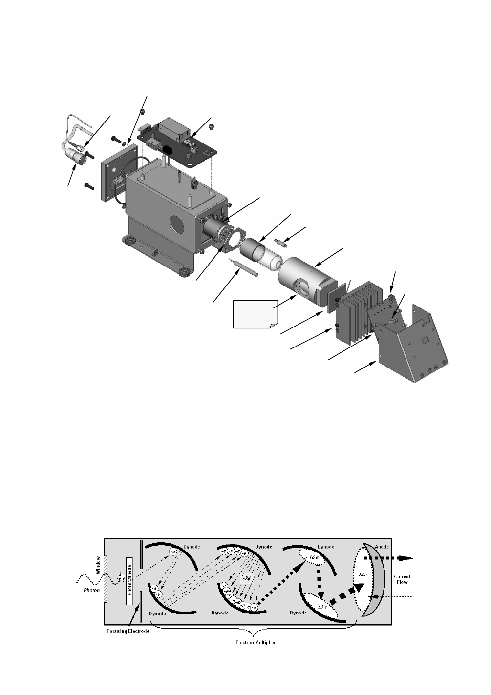
A typical PMT is a vacuum tube containing a variety of specially designed electrodes. Photons from the reaction
are filtered by an optical high-pass filter, enter the PMT and strike a negatively charged photo cathode causing it
to emit electrons. A high voltage potential across these focusing electrodes directs the electrons toward an
array of high voltage dynodes. The dynodes in this electron multiplier array are designed so that each stage
multiplies the number of emitted electrons by emitting multiple, new electrons. The greatly increased number of
electrons emitted from one end of electron multiplier are collected by a positively charged anode at the other
end, which creates a useable current signal. This current signal is amplified by the preamplifier board and then
reported to the motherboard.
Figure 10-10-19: Basic PMT Design
04521C (DCN5731)