


Troubleshooting & Repair Teledyne API - Model 200EH/EM Operation Manual
244
Check for actual sample flow. To check the actual sample flow, disconnect the sample tube from the
sample inlet on the rear panel of the instrument. Make sure that the unit is in basic SAMPLE mode.
Place a finger over the inlet and see if it gets sucked in by the vacuum or, more properly, use a flow
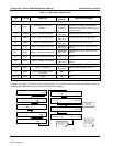
meter to measure the actual flow. If there is proper flow (see Table 10-3 for flow rates), contact
customer service. If there is no flow or low flow, continue with the next step.
Check pressures. Check that the sample pressure is at or around 28 in-Hg-A at sea level (adjust as
necessary when in elevated location, the pressure should be about 1” below ambient atmospheric
pressure) and that the RCEL pressure is below 10 in-Hg-A. The M200EH/EM will calculate a sample
flow up to about 14 in-Hg-A RCEL pressure but a good pump should always provide less than 10 in.
If both pressures are the same and around atmospheric pressure, the pump does not operate
properly or is not connected properly. The instrument does not get any vacuum.
If both pressures are about the same and low (probably under 10 in-Hg-A, or ~20” on sample and 15”
on vacuum), there is a cross-leak between sample flow path and vacuum, most likely through the
Perma Pure dryer flow paths. See troubleshooting the Perma Pure dryer later in this chapter.
If the sample and vacuum pressures are around their nominal values (28 and <10 in-Hg-A,
respectively) and the flow still displays
XXXX, carry out a leak check as described in Section 0
If gas flows through the instrument during the above tests but goes to zero or is low when it is connected
to zero air or span gas, the flow problem is not internal to the analyzer but likely caused by the gas
source such as calibrators/generators, empty gas tanks, clogged valves, regulators and gas lines.
If an IZS or Zero/Span valve option is installed in the instrument, press
CALZ and CALS. If the sample
flow increases, suspect a bad Sample/Cal valve.
If none of these suggestions help, carry out a detailed leak check of the analyzer as described in Section
0.
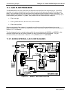
11.2.3.2. Ozone Flow is Zero or Low
If there is zero or a low (<200 cm³/min) ozone flow, the unit displays an OZONE FLOW WARNING message on
the front panel and a value between 0.0 and 200 cm³/min for the actual ozone flow as measured by the internal
mass flow meter. In this case, carry out the following steps:
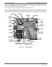
Check the actual flow rate through the ozone dryer by using an external flow meter to the inlet port of the
dryer. This inlet port is inside the analyzer at the end of the plastic particle filter (Section 9.3.2 for
illustration). If there is nom
inal flow (see Table 10-3 for flow rates), consult customer service as there is
a problem with the firmwa
re or electronics.
If the actual flow is low or zero, check if the pump operates properly. The
RCEL pressure should be
below 10 in-Hg-A at sea level. If it is above 10”, rebuild the pump (Section 9.3.3). Check the spare
parts list in Appendix B on how to order pump rebuild kits.
Chec
k if the particle filter is clogged.
Briefly remove the particle filter to see if this improves the flow.
Be very cautious about handling the Perma Pure dryer fittings - refer to Section 9.3.2 on proper handling
instructions. If the filter is clogged, replace it with a n
ew unit. If taking off this filter does not solve the
problem, continue to the next step. Do not leave the Perma Pure dryer without filter for more than a few
seconds, as you may draw in dust, which will reduce the performance of the dryer.
A leak between the flow meter and the reaction cell (where the flow-determining critical orifice is located)
may cause a low flow (the system draws in ambient air through a leak after the flow meter). Check for
leaks as described in Section 0. Repair the leaking fitting, line or valve and re-check.
04521C (DCN5731)