


Getting Started Teledyne API - Model 200EH/EM Operation Manual
12
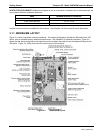
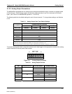
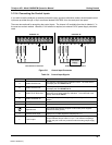
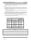
3.1.2.3. Connecting the Status Outputs
If you wish to utilize the analyzer’s status outputs to interface with a device that accepts logic-level digital inputs,
such as programmable logic controller (PLC) chips, you can access them through a 12 pin connector on the
analyzer’s rear panel labeled STATUS.
EMITTER BUS
FOR PINS 1-8
STATUS
1 2 3 4 5 6 7 8 D +
SYSTEM OK
HIGH RANGE
CONC VALID
ZERO CAL
SPAN CAL
DIAGNOSTIC
MODE
LOW SPAN
Figure 3-5: Status Output Connector
NOTE
Most PLC’s have internal provisions for limiting the current the input will draw. When
connecting to a unit that does not have this feature, external resistors must be used to
limit the current through the individual transistor outputs to ≤50mA (120 Ω for 5V
supply).
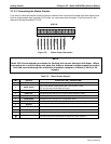
Table 3-3: Status Output Signals
PIN # STATUS CONDITION (ON = CONDUCTING)
1
SYSTEM OK
ON if no faults are present.
2
CONC VALID
ON if concentration measurement (NO, NO2 or NOx) is valid.
OFF any time the hold-off feature is active.
3
HIGH RANGE
ON if unit is in high range of the Auto Range Mode.
4
ZERO CAL
ON whenever the instrument is in ZERO point calibration mode.
5
SPAN CAL
ON whenever the instrument is in SPAN point calibration mode.
6
DIAG MODE
ON whenever the instrument is in diagnostic mode.
7
LOW SPAN CAL
ON when in low span calibration (optional equipment necessary)
8
Unused
D
EMITTER BUS
The emitters of the transistors on pins 1-8 are tied together.
Unused
+
DC POWER
+ 5 VDC, 300 mA (combined rating with Control Output, if used).
Digital Ground
The ground level from the analyzer’s internal DC power supplies
04521C (DCN5731)