Getting Started Teledyne API - Model 200EH/EM Operation Manual
20
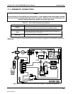
VENT here if input
is pressurized
Source of
SAMPLE Gas
PUMP
VENT
MODEL
200EH/EM
Sample
Exhaust
High Span Point
Low Span Point
Zero Air
Calibrated NO
at HIGH Span
Concentration
Calibrated NO
at LOW Span
Concentration
Filter
External Zero
Air Scrubbe
r
VENT
On/Off
Valves
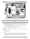
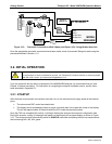
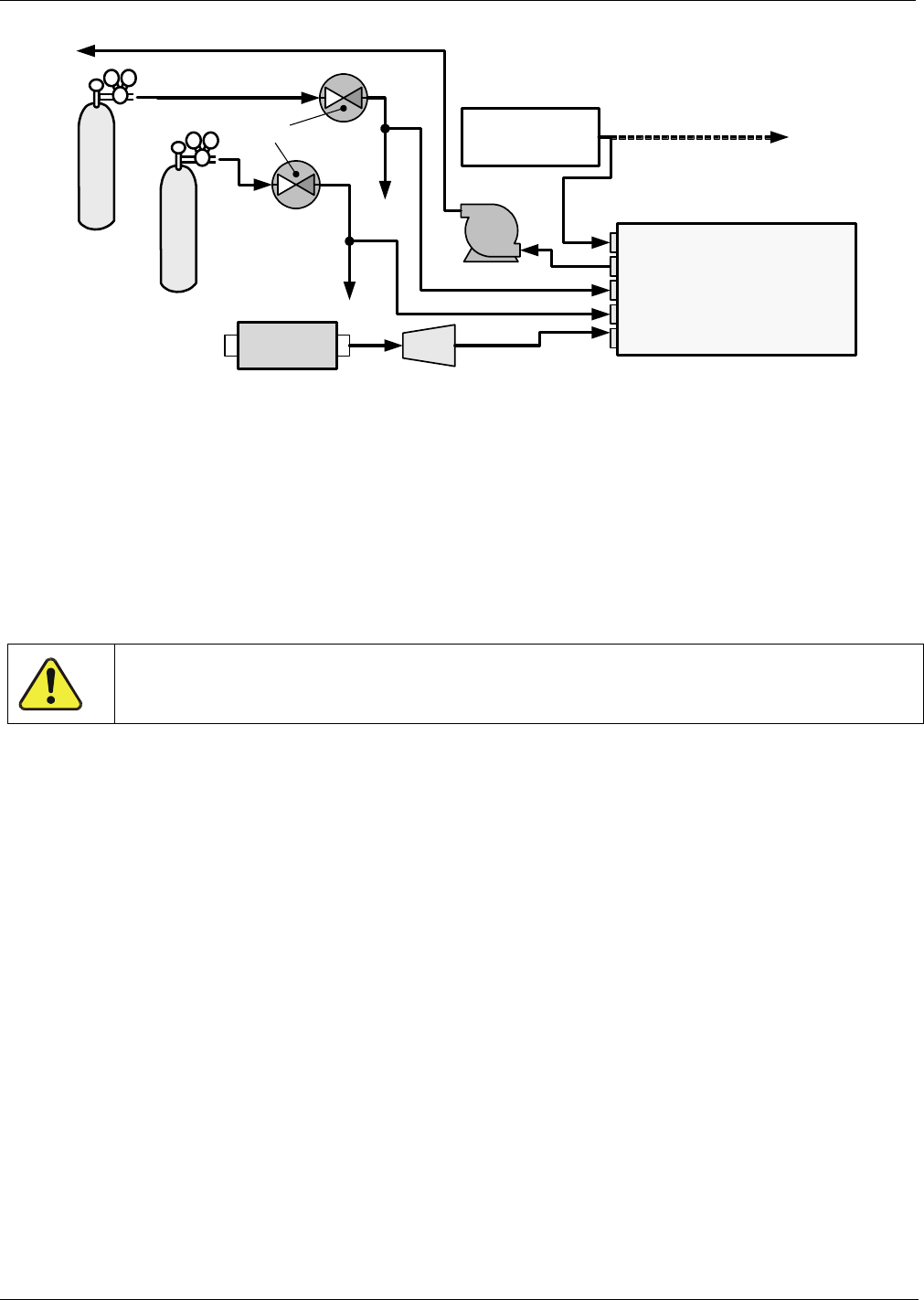
Figure 3-12: Pneumatic Connections–With 2-Span point Option (52) –Using Bottled Span Gas
Once the appropriate pneumatic connections have been made, check all pneumatic fittings for leaks using the
procedures defined in Section 11.5.
3.2. INITIAL OPERATION
CAUTION!
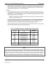
If the presence of ozone is detected at any time, call Teledyne API Customer Service as soon as possible:
800-324-5190 or email: api-customerservice@teledyne.com
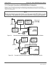
If you are unfamiliar with the theory of operation of the M200EH/EM analyzer, we recommend that you read
Chapter 10 before proceeding. For information on navigating the analyzer’s software menus, see the me
nu
trees described in Appendix A-1.
3.2.1. STARTUP
After electrical and pneumatic connections are made, turn on the instrument and supply power to the external
pump.
The exhaust and PMT cooler fans should start.
The display should immediately display a single, horizontal dash in the upper left corner of the display.
This will last approximately 30 seconds while the CPU loads the operating system.
Once the CPU has completed this activity, it will begin loading the analyzer firmware and configuration data.
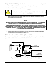
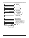
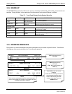
During this process, a string of messages will appear on the analyzer’s front panel display as shown in Figure
3-13. The analyzer should
automatically switch to SAMPLE mode after completing the boot-up sequence and
start monitoring NO
X
, NO, NO
2
gases.
04521C (DCN5731)


