


Teledyne API - Model 200EH/EM Operation Manual Operating Instructions
113
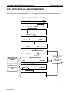
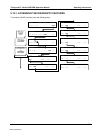
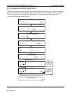
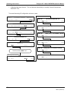
6.13.5. ANALOG I/O CONFIGURATION
6.13.5.1. The Analog I/O Configuration Submenu.
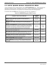
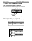
Table 6-21 lists the analog I/O functions that are available in the M200EH/EM.
Table 6-21: DIAG - Analog I/O Functions
SUB MENU FUNCTION
AOUTS
CALIBRATED:
Shows the status of the analog output calibration (YES/NO) and initiates a calibration
of all analog output channels.
DATA_OUT_1:
Configures the A1 analog output:
RANGE
1
: Selects the signal type (voltage or current loop) and full scale value of the
output.
OVERRANGE: Turns the ± 5% over-range feature ON/OFF for this output channel.
REC_OFS
1
: Sets a voltage offset (not available when RANGE is set to CURRent loop.
AUTO_CAL
1
: Sets the channel for automatic or manual calibration
CALIBRATED
1
: Performs the same calibration as AOUT CALIBRATED, but on this
one channel only.
OUTOUT: Turns the output channel ON/OFF. A signal. Equal to the low end of the
output scale (zero point) is still output by the analyzer, but no data is sent.
DATA: Allows the user to select which iDAS parameter to be output.
SCALE: Sets the top end of the reporting range scale for this channel. The analyzer
automatically chooses the units of measure appropriate for the iDAS parameter chosen
(e.g. ppm for concentration parameters; in-Hg-A for pressure measurements, etc.)
UPDATE: Sets the time interval at which the analyzer updates the data being output
on the channel.
DATA_OUT_2
Same as forDATA_OUT_1 but for analog channel 2 (NO)
DATA_OUT_3
Same as for DATA_OUT_1 but for analog channel 3 (NO
2
)
DATA_OUT_4
Same as for DATA_OUT_1 but for analog channel 3 (NO
2
)
TEST OUTPUT
Same as for DATA_OUT_1 but for analog channel 4 (TEST)
AIN CALIBRATED Shows the calibration status (YES/NO) and initiates a calibration of the analog to digital
converter circuit on the motherboard.
1
Changes to RANGE or REC_OFS require recalibration of this output.
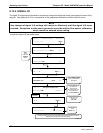
To configure the analyzer’s four analog outputs, set the electronic signal type of each channel and calibrate the
outputs. This consists of:
1. Selecting an output type (voltage or current, if an optional current output driver has been installed) and
the signal level that matches the input requirements of the recording device attached to the channel.
2. Determine if the over-range feature is needed and turn it on or off accordingly.
3. If a Voltage scale is in use, a bipolar recorder offset may be added to the signal if required (Section
6.13.4.4).
4. Choose an iDAS parameter to be output on the channel.
5. Set the reporting range scale for the data type chosen.
6. Set the update rate for the channel.
04521C (DCN5731)