


Instrument Maintenance Teledyne API - Model 200EH/EM Operation Manual
186
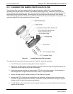
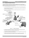
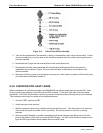
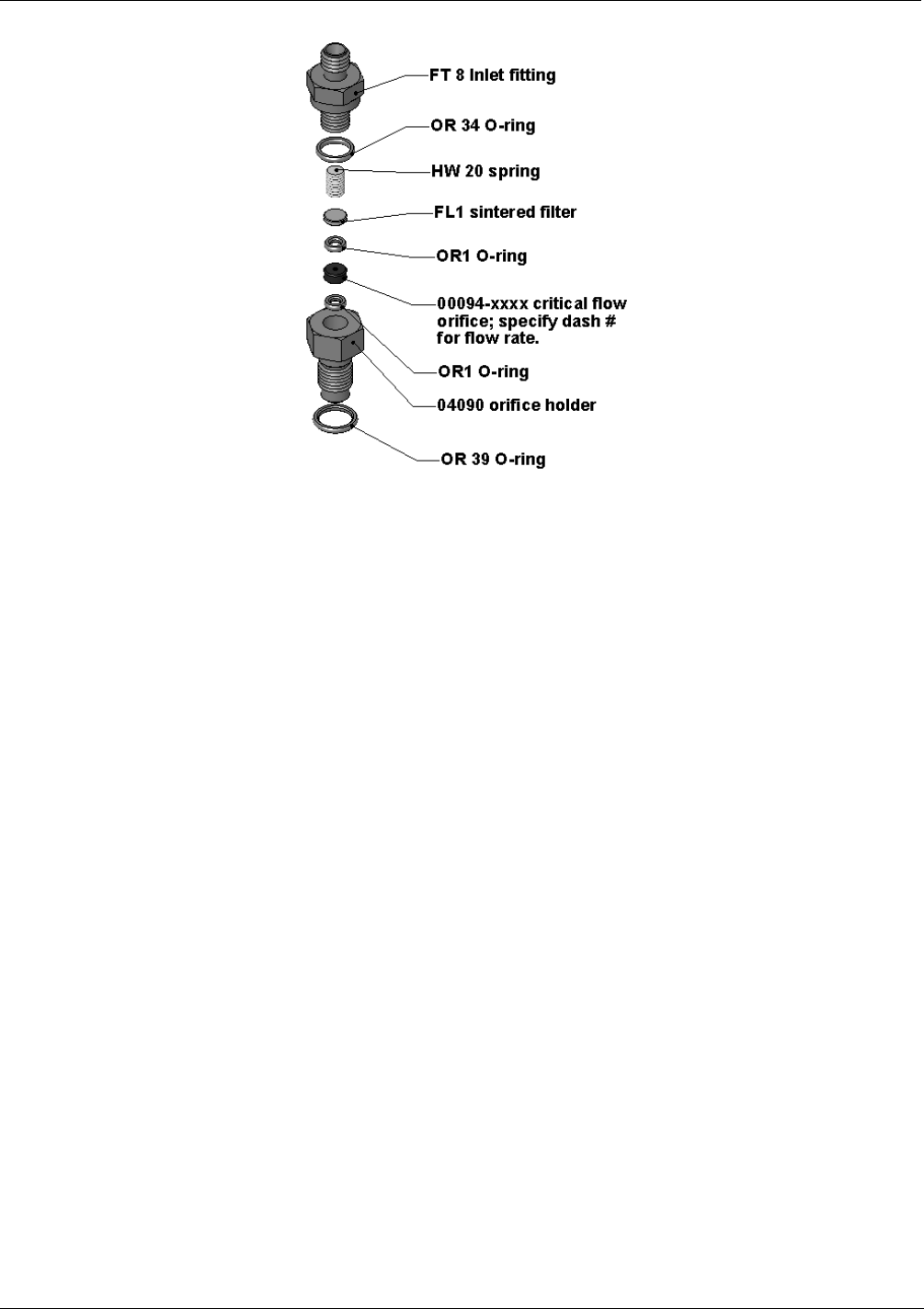
Figure 9-6: Critical Flow Orifice Assembly
5. Take out the components of the assembly: a spring, a sintered filter, two O-rings and the orifice. For the
vacuum manifold only, you may need to use a scribe or pressure from the vacuum port to get the parts
out of the manifold.
6. Discard the two O-rings and the sintered filter and the critical flow orifice.
7. Re-assemble the flow control assembly with new the parts (see Appendix B for part number or
replacement kit) as shown in Figure 9-6 and re-connect them to the reaction cell manifold or the
vacuum manifold.
8. Reconne
ct all tubing, power up the analyzer and pump and - after a warm-up period of 30 minutes, carry
out a leak test as described in Section 0.
9.3.9. CHECKING FOR LIGHT LEAKS
When re-assembled or operated improperly, the M200EH/EM can develop small leaks around the PMT, which
let stray light from the analyzer surrounding into the PMT housing. To find such light leaks, follow the below
procedures. CAUTION: this procedure can only be carried out with the analyzer running and its cover removed.
This procedure should only be carried out by qualified personnel.
1. Scroll the TEST functions to PMT.
2. Supply zero gas to the analyzer.
3. With the instrument still running, carefully remove the analyzer cover. Take extra care not to touch any
of the inside wiring with the metal cover or your body. Do not drop screws or tools into a running
analyzer!
4. Shine a powerful flashlight or portable incandescent light at the inlet and outlet fitting and at all of the
joints of the reaction cell as well as around the PMT housing. The PMT value should not respond to the
light, the PMT signal should remain steady within its usually noise.
04521C (DCN5731)