


Teledyne API - Model 200EH/EM Operation Manual Theory of Operation
213
A significant performance characteristic of the PMT is the voltage potential across the electron multiplier. The
higher the voltage, the greater is the number of electrons emitted from each dynode of the electron multiplier,
making the PMT more sensitive and responsive to small variations in light intensity but also more noisy (dark
noise). The gain voltage of the PMT used in the M200EH/EM is usually set between 450 V and 800 V. This
parameter is viewable through the front panel as test function
HVPS (see Section 6.2.1). For information on
when and how to set this voltage, see Section 11.6.3.8.
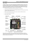
The PMT is housed inside the PMT module assembly (see Figure 10-18). This assembly also includes the high
voltage power supply required to drive the PMT, an LED used by the instrument’s optical test function, a
thermistor that measures the temperature of the PMT and various components of the PMT cooling system
including the thermo-electric cooler (TEC).
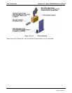
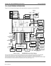
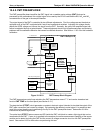
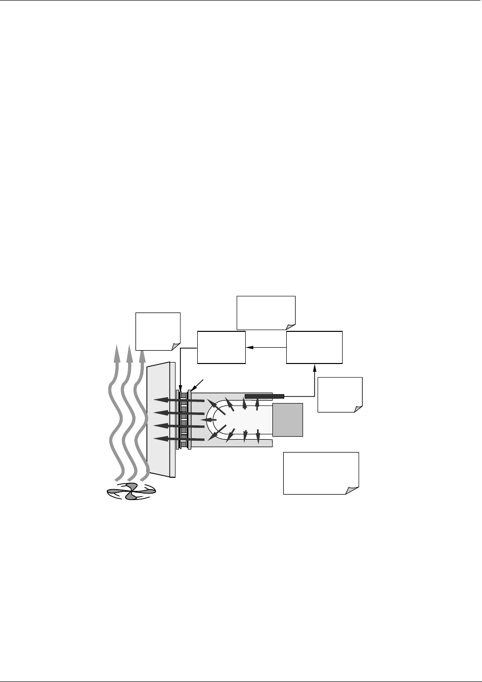
10.4.4. PMT COOLING SYSTEM.
The performance of the analyzer’s PMT is significantly affected by temperature. Variations in PMT temperature
are directly reflected in the signal output of the PMT. Also the signal to noise ratio of the PMT output is radically
influenced by temperature as well. The warmer The PMT is, the noisier its signal becomes until the noise
renders the concentration signal useless. To alleviate this problem a special cooling system exists that
maintains the PMT temperature at a stable, low level
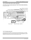
TEC
Control
PCA
PMT Preamp
PCA
Thermistor
out
p
uts tem
p
of
cold block to
preamp PCA
Preamp PCA sends
buffered and
amplified thermistor
signal to TEC PCA
TEC PCA sets
appropriate
drive voltage
for cooler
Heat form PMT is absorbed
by the cold block and
transferred to the heat sink
via the TEC then bled off
into the cool air stream.
PMT
Cold Block
Heat Sink
Cooling Fan
ThermoElectric Cooler
Figure 10-10-20: PMT Cooling System
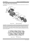
10.4.4.1. TEC Control Board
The TEC control printed circuit assembly is located ion the sensor housing assembly, under the slanted shroud,
next to the cooling fins and directly above the cooling fan. Using the amplified PMT temperature signal from the
PMT preamplifier board (see Section 10.4.5), it sets the drive voltage for the thermoelectric cooler. The warmer
the PMT gets, the more current is passed through the TEC causing it to pump more heat to the heat sink.
A red LED located on the top edge of this circuit board indicates that the control circuit is receiving power. Four
test points are also located at the top of this assembly. For the definitions and acceptable signal levels of these
test points see Chapter 11.
04521C (DCN5731)