


Teledyne API - Model 200EH/EM Operation Manual Theory of Operation
201
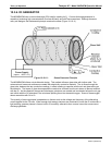
In addition to controlling the gas flows, the two critical flow orifices at the inlets of the reaction cell also maintain
an under-pressure inside the reaction cell, effectively reducing the number of molecules in the chamber and
therefore increasing the chemiluminescence yield as the likelihood of third body quenching is reduced (Section
10.2.4.1). The M200EH/EM sensitivity reache
s a peak at about 2 in-Hg-A, below
which the sensitivity drops due
to a low number of molecules and decreased yield in the chemiluminescence reaction.
EFFECT OF TEMPERATURE ON CRITICAL FLOW
Changes in temperature will cause the critical flow orifice materials to expand or contract. Even though these
changes are extremely small, they can alter the diameter of the critical flow orifice enough to cause noticeable
changes in the flow rate though the orifice. To alleviate this problem the two most important of the flow
assemblies (those controlling the sample gas an O
3
gas flow)in the M200EH/EM are maintained at a constant
temperature.
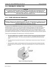
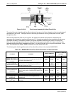
10.3.4. SAMPLE PARTICULATE FILTER
To remove particles in the sample gas, the analyzer is equipped with a 5PTFE membrane filter of 47 mm
diameter (also referred to as the sample filter) with a 1 µm pore size. The filter is accessible through the front
panel, which folds down (after removal of the CE Mark safety screw), and should be changed according to the
maintenance schedule in Table 9-1.
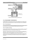
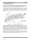
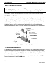
10.3.5. OZONE GAS AIR FLOW
The excess ozone needed for reaction with NO in the reaction cell is generated inside the analyzer because of
the instability and toxicity of ozone. Besides the ozone generator itself, this requires a dry air supply and filtering
of the gas before it is introduced into the reaction cell. Due to its toxicity and aggressive chemical behavior, O
3
must also be removed from the gas stream before it can be vented through the exhaust outlet.
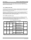
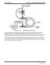
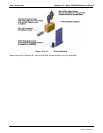
In contrast to the sample flow, the ozone flow is measured with a mass flow sensor, which is mounted on the
pneumatic sensor board (Figure 11-), just behind the PMT sensor assembly. This mass flow sensor has a full
scale range of 0-1000 cm³/min and can be cali
brated through software to its span point (Section 6.13.7.5). As
the flow value displayed on the front panel is an actual
measurement (and not a calculated value), the flow
variability may be higher than that of the sample flow, which is based on a calculation from (more stable)
differential pressures. On the other hand, the drift, i.e. long-term change, in the ozone flow rate may be higher
and usually indicates a flow problem. As with all other test parameters, we recommend to monitor the ozone
flow over time for predictive diagnostics and maintenance evaluation.
CAUTION
Ozone (O
3
) is a toxic gas. Obtain a Material and Safety Data Sheet
(MSDS) for this gas. Read and rigorously follow the safety guide-
lines described there. Always make sure that the plumbing of the
O
3
generation and supply system is maintained and leak-free.
04521C (DCN5731)