


Getting Started Teledyne API - Model 200EH/EM Operation Manual
8
VENTILATION CLEARANCE: Whether the analyzer is set up on a bench or installed into an instrument rack, be
sure to leave sufficient ventilation clearance.
AREA MINIMUM REQUIRED CLEARANCE
Back of the instrument 10 cm / 4 inches
Sides of the instrument 2.5 cm / 1 inch
Above and below the instrument. 2.5 cm / 1 inch
Various rack mount kits are available for this analyzer. See Chapter 5 of this manual for more information.
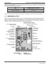
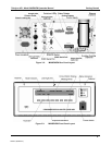
3.1.1. M200EH/EM LAYOUT
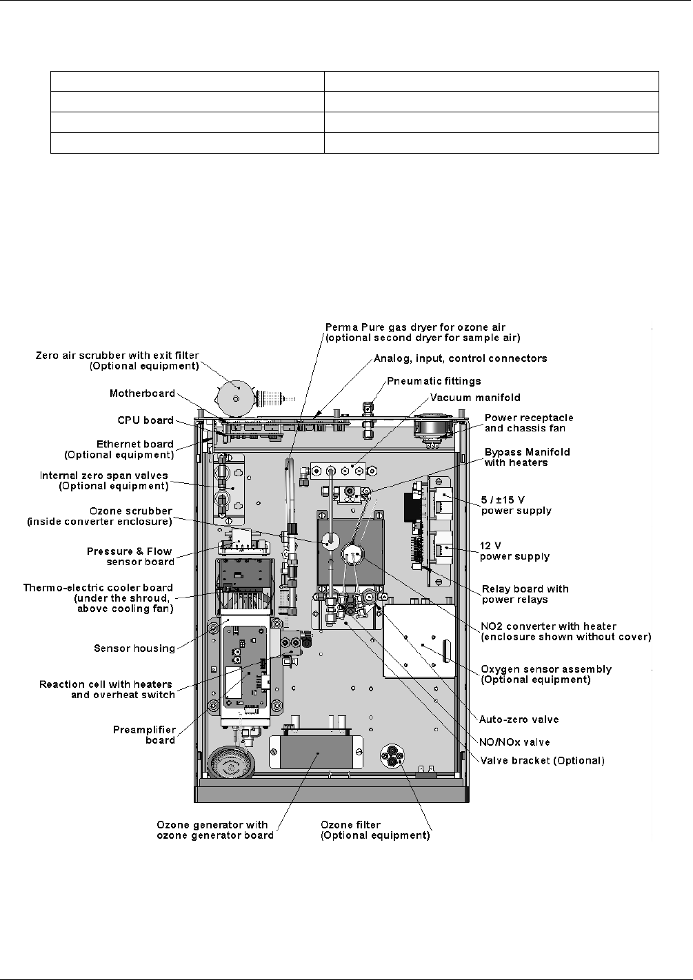
Figure 3-1 shows a top-down view of the analyzer. The shown configuration includes the Ethernet board, IZS
option, zero-air scrubber and an additional sample dryer. See Chapter 5 for optional equipment. Figure 3-2
shows the rear panel configuration with
optional zero-air scrubber mounted to it and two optional fittings for the
IZS option. Figure 3-3, finally shows the front panel la
yout of the analyzer.
Figure 3-1: M200EH/EM Layout
04521C (DCN5731)