Teledyne API - Model 200EH/EM Operation Manual Operating Instructions
127
6.13.6.2. Manual Calibration of Analog Output configured for Voltage Ranges
For highest accuracy, the voltages of the analog outputs can be manually calibrated.
NOTE:
The menu for manually adjusting the analog output signal level will only appear if the
AUTO-CAL feature is turned off for the channel being adjusted (see Section 6.13.5.1)
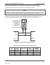
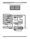
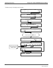
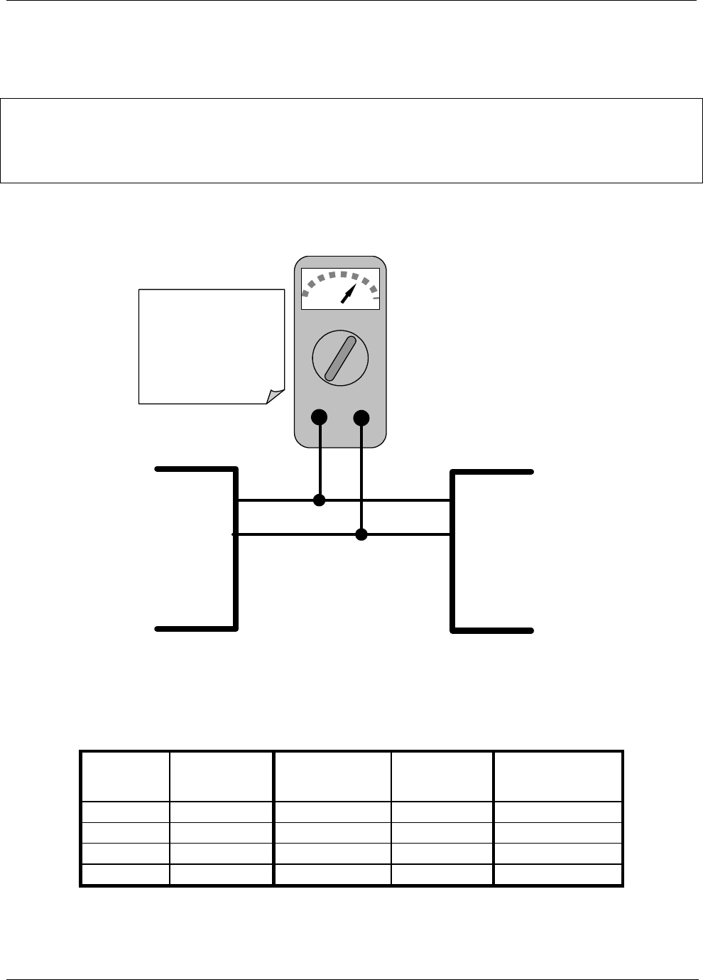
Calibration is performed with a voltmeter connected across the output terminals (See Figure 6-14) and by
changing the actual output signal level using the front panel keys in 100, 10 or 1 count increments.
V
+DC Gnd
V OUT +
V OUT -
V IN +
V IN -
Recording
Device
ANALYZER
See Table 3-1 for
pin assignments
of Analog Out
connector on the
rear panel
Figure 6-6-14: Setup for Calibrating Analog Outputs
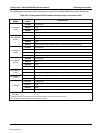
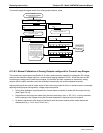
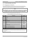
Table 6-24: Voltage Tolerances for Analog Output Calibration
FULL
SCALE
ZERO
TOLERANCE
SPAN VOLTAGE
SPAN
TOLERANCE
MINIMUM
ADJUSTMENT
(1 count)
0.1 VDC ±0.0005V 90 mV ±0.001V 0.02 mV
1 VDC ±0.001V 900 mV ±0.001V 0.24 mV
5 VDC ±0.002V 4500 mV ±0.003V 1.22 mV
10 VDC ±0.004V 4500 mV ±0.006V 2.44 mV
04521C (DCN5731)


