


Teledyne API - Model 200EH/EM Operation Manual Optional Hardware and Software
39
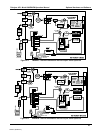
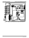
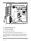
5.4. CURRENT LOOP ANALOG OUTPUTS (OPT 41)
This option adds isolated, voltage-to-current conversion circuitry to the analyzer’s analog outputs. This option
may be ordered separately for the first three of the analog outputs and can be installed at the factory or added
later. Call Teledyne Instruments sales for pricing and availability.
The current loop option can be configured for any output range between 0 and 20 mA (for example 0-20, 2-20 or
4-20 mA). Information on calibrating or adjusting these outputs can be found in Section 6.13.5.3.
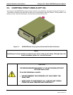
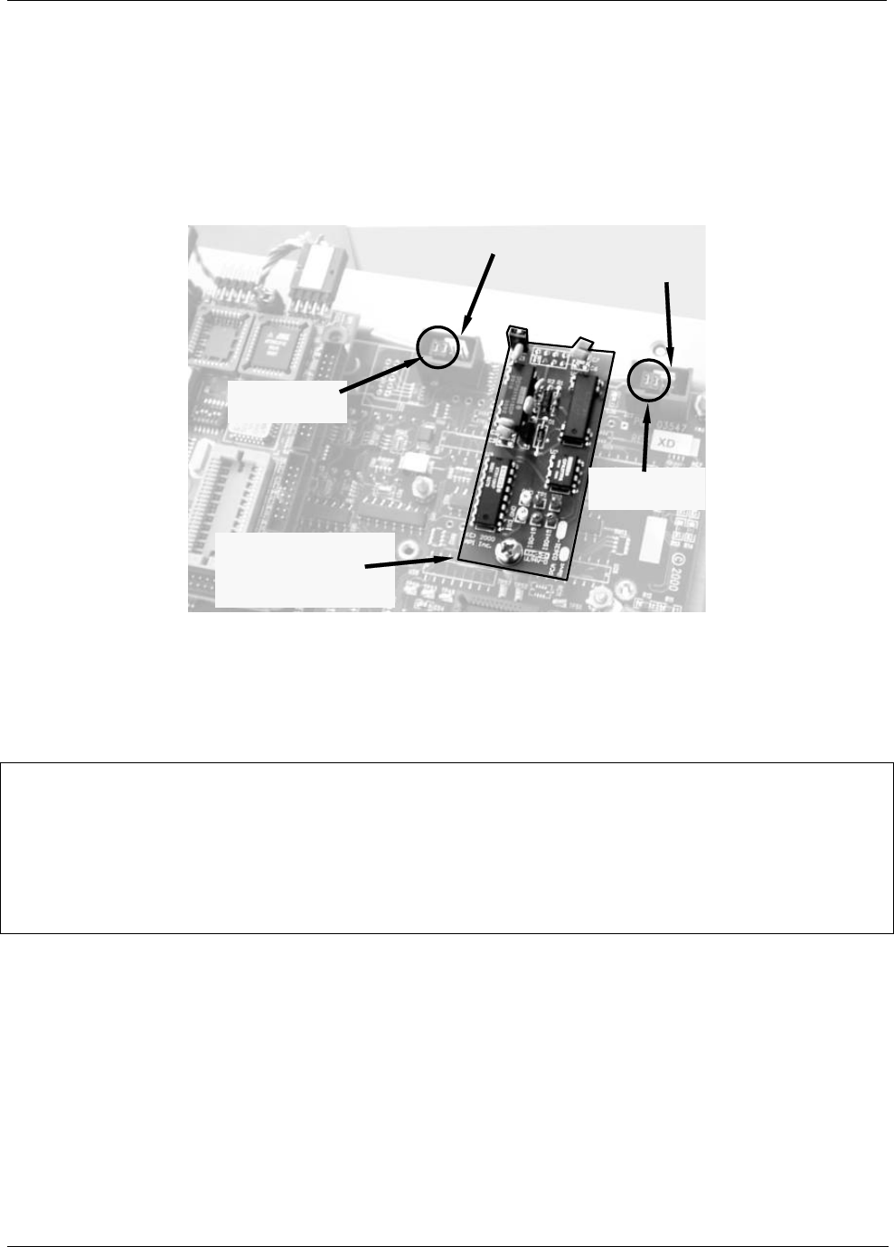
Analog Output A2
Current Loop Option
Installed on J21
(Analog Output A2)
J 23
J19
V
oltage Output
Shunts installed
V
oltage Output
Shunts installed
Figure 5-2: Current Loop Option Installed on the Motherboard
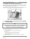
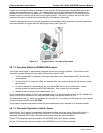
5.4.1. CONVERTING CURRENT LOOP ANALOG OUTPUTS TO STANDARD
VOLTAGE OUTPUTS.
NOTE
Servicing or handling of circuit components requires electrostatic discharge protection,
i.e. ESD grounding straps, mats and containers. Failure to use ESD protection when
working with electronic assemblies will void the instrument warranty.
See Chapter 12 for more information on preventing ESD damage.
To convert an output configured for current loop operation to the standard 0 to 5 VDC output operation:
5. Turn off power to the analyzer.
6. If a recording device was connected to the output being modified, disconnect it.
7. Remove the top cover
Remove the set screw located in the top, center of the rear panel
Remove the screws fastening the top cover to the unit (four per side).
Lift the cover straight up.
8. Disconnect the current loop option PCA from the appropriate connector on the motherboard.
04521C (DCN5731)