


Theory of Operation Teledyne API - Model 200EH/EM Operation Manual
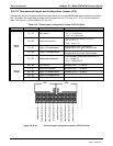
220
NO
2
CONVERTER TEMPERATURE: This parameter is measured with a Type-K thermocouple attached to the
NO
2
converter heater and its analog signal is amplified by the circuitry on the relay board. It is sent to the CPU
and then digitized and is used to calculate the current temperature of the NO
2
converter. It is also stored in the
iDAS and reported as test function
MOLY TEMP.
SAMPLE GAS PRESSURE: This is measured upstream of the reaction cell, stored in the iDAS and reported as
SAMPLE. The vacuum gas pressure is measured downstream of the reaction cell and is stored in the iDAS and
reported as
RCEL. For more information on these sensor’s functions see Section 10.3.10.
O
3
GAS FLOW This sensor measures the gas flow upstream of the ozone generator, stored in the iDAS and
reported as test function
OZONE FL. For more information on this sensor’s function see Section 10.3.10.
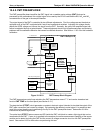
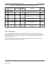
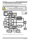
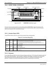
10.4.9.3. Thermistor Interface
This circuit provides excitation, termination and signal selection for several negative-coefficient, thermistor
temperature sensors located inside the analyzer. They are:
REACTION CELL TEMPERATURE SENSOR A thermistor embedded in the reaction cell manifold. This
temperature is used by the CPU to control the reaction cell heating circuit and as a parameter in the
temperature/pressure compensation algorithm. This measurement is stored in the analyzer’s iDAS and reported
as test function
RCEL TEMP.
BOX TEMPERATURE SENSOR: A thermistor is attached to the motherboard. It measures the analyzer’s inside
temperature. This information is stored by the CPU and can be viewed by the user for troubleshooting purposes
through the front panel display. It is also used as part of the NO, NO
X
and NO
2
calculations when the
instrument’s Temperature/Pressure Compensation feature is enabled. This measurement is stored in the
analyzer. Memory as the test function
BOX TEMP and is viewable as a test function (Section 6.2.1) through the
analyzer’s front panel.
The thermistor inside the PMT cold block as well as the thermistor located on the preamplifier board are both
converted to analog signals on the preamplifier board before being sent to the motherboard’s A/D converter.
O
2
SENSOR TEMPERATURE: For instruments with the oxygen sensor option installed, the thermistor
measuring the temperature of the heating block mounted to the sensor is reported as test function
O2 TEMP on
the front panel. This temperature is maintained at 50° C.
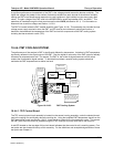
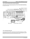
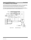
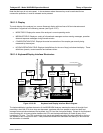
10.4.10. ANALOG OUTPUTS
The analyzer comes equipped with four Analog Outputs: A1, A2, A3 and a fourth that is a spare.
A1 and A2 Outputs: The first two, A1 and A2 are normally set up to operate in parallel so that the same data can
be sent to two different recording devices. While the names imply that one should be used for sending data to a
chart recorder and the other for interfacing with a datalogger, either can be used for both applications.
Output Loop-back
: All of the functioning analog outputs are connected back to the A/D converter through a
Loop-back circuit. This permits the voltage outputs to be calibrated by the CPU without need for any additional
tools or fixtures (see Section 6.13.5.4)
04521C (DCN5731)