


Teledyne API - Model 200EH/EM Operation Manual Theory of Operation
215
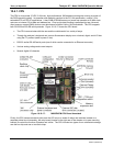
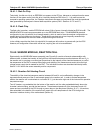
10.4.6. PNEUMATIC SENSOR BOARD
The flow and pressure sensors of the M200EH/EM are located on a printed circuit assembly just behind the PMT
sensor. Refer to Section 11.5.15 for information on how to test this assembly. The signals of this board are
supplied to the motherboard for further signal processing. All senso
rs are linearized in the firmware and can be
span calibrated from the front panel.
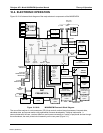
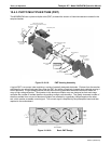
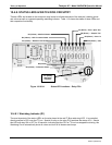
10.4.7. RELAY BOARD
The relay board is the central switching and power distribution unit of the analyzer. It contains power relays,
valve drivers and status LEDs for all heated zones and valves, as well as thermocouple amplifiers, power
distribution connectors and the two switching power supplies of the analyzer. The relay board communicates
with the motherboard over the I
2
C bus and can be used for detailed trouble-shooting of power problems and
valve or heater functionality. See Figure 11-4 for an annotated view of the relay board.
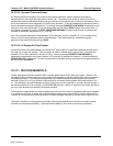
10.4.7.1. Relay PCA Location and Layout
Generally the relay PCA is located in the right-rear quadrant of the analyzer and is mounted vertically on the
back side of the same bracket as the instrument’s DC power supplies, however the exact location of the relay
PCA may differ from model to model (see Figure 3-1)
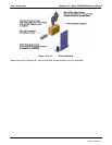
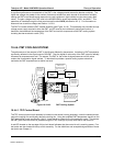
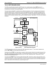
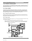
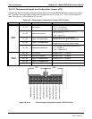
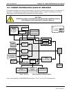
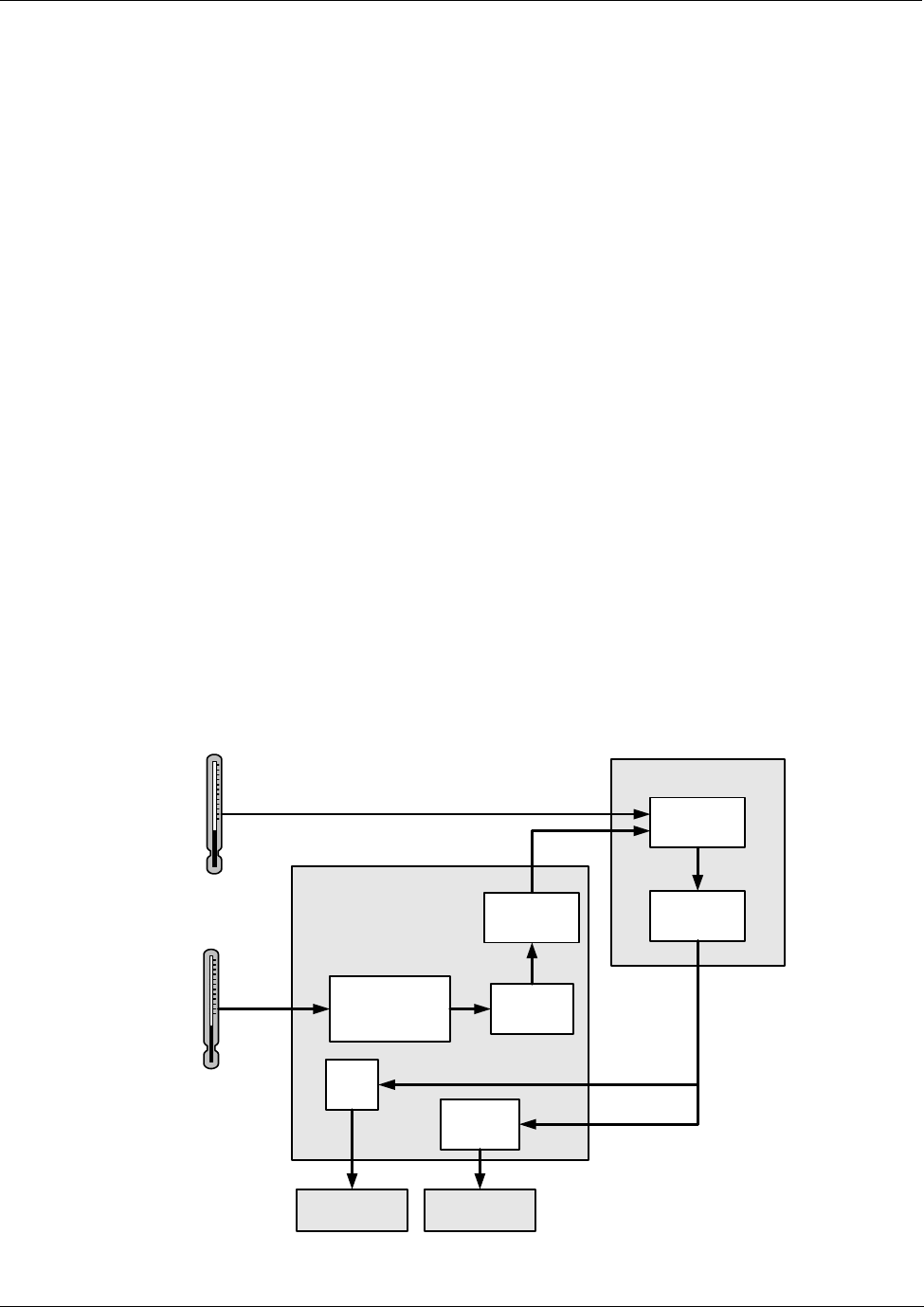
10.4.7.2. Heater Control
The heater control loop is illustrated in Figure 10-22. Two T/C inputs can be configured for either type-T or type-
K thermocouples. Additionally:
Both T/C’s can be configured as either grounded or ungrounded thermocouples.
Standard configuration of the both type of thermocouples is 10 mV/°C. In order to accommodate the
M200EH’s Mini High-Con converter option, a type-K; 5mV/°C output configuration has been added.
Thermistor(s) – Low Temperature Sensing:
(e.g. Sample Chamber and Reaction
Cell temperatures)
RELAY PCA
DC
Control
Logic
Solid State
AC Relays
Preamplifiers
and Signal
Conditioning
MOTHER BOARD
A/D
Converter
(V/F)
CPU
Themocouple(s)
(High Temperature Sensing;
e.g. Moly and HiCon
Converter temperatures)
AC HEATERSDC HEATERS
THERMOCOUPLE
CONFIGURATION
JUMPER
(JP5)
Cold Junction
Compensation
Figure 10-10-22: Heater Control Loop Block Diagram.
04521C (DCN5731)