


Teledyne API - Model 200EH/EM Operation Manual Theory of Operation
209
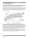
10.4. ELECTRONIC OPERATION
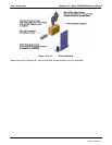
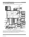
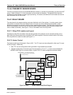
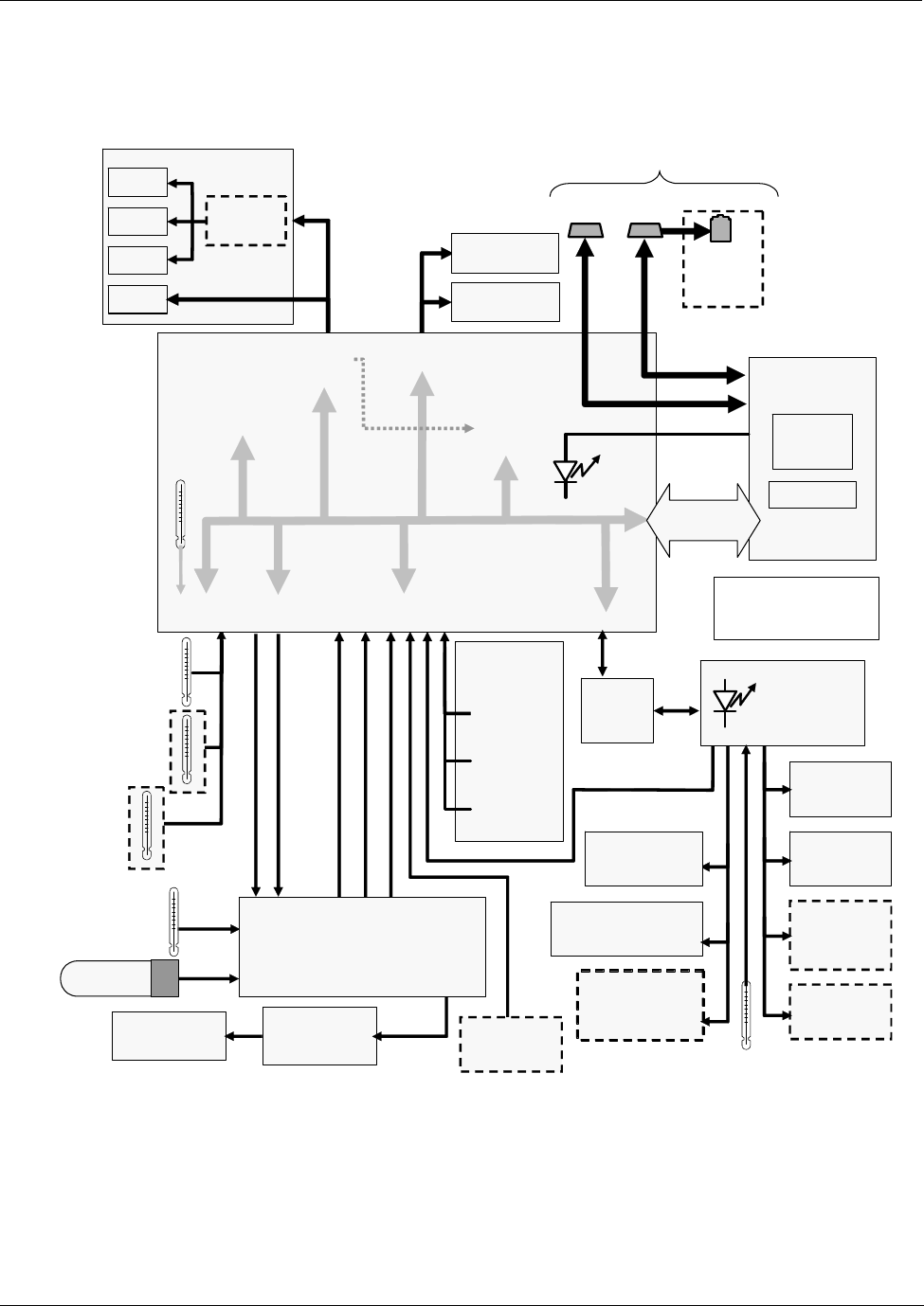
Figure 10-10-16 shows a block diagram of the major electronic components of the M200EH/EM.
Back Panel
Connectors
Optional
Ethernet
Interface
Pneumatic
Sensor
Board
Sample
Pressure
Sensor
Vacuum
Pressure
Sensor
O
3
Flow Sensor
Analog Outputs
Status Outputs:
1 – 8
Control Inputs:
1 – 6
PC 104
CPU Card
Disk On
Chip
Flash Chip
RS–232 ONLY
RS–232 or RS–485
Power-Up
Circuit
I
2
C Bus
Analog
Sensor Inputs
Box
Temp
Thermistor
Interface
REACTION CELL
TEMPERATURE
MOLYBDENUM CONVERTER
TEMPERATURE
PMT
Temperature
Sensor
A1
A2
A3
Optional
4-20 mA
MOTHER
BOARD
A/D
Converter(
V/F)
PC 104
Bus
External
Digital I/O)
COM1
Analog
Outputs
(D/A)
Keybd &
Display
RELAY
BOARD
I
2
C Status
LED
PUMP
(Externally Powered)
A4
COM2
CPU STATUS
LED
NO/NO
x
Valve
IZS OPTION
PERMEATION TUBE
TEMPERATURE
Autozero
Valve
Sample Cal
Valve Option
Option
IZS Valve
Option
Reaction Cell
Heater
Molybdenum
Converter Heater
IZS Option
Permeation Tube
Heater
PMT TEC
PMT
MOLYBDENUM CONVERTER
TEMPERATURE SIGNAL
TEC Drive
PCA
Internal
Digital I/O
ELECTRIC TEST CONTROL
OPTIC TEST CONTROL
PMT OUTPUT (PMT DET)
O
2
Sensor
Option
HIGH VOLTAGE POWER SUPPLY LEVEL
PMT TEMPERATURE
PMT
PREAMP PCA
O
2
OPTION
TEMPERATURE
Figure 10-10-16: M200EH/EM Electronic Block Diagram
The core of the analyzer is a microcomputer (CPU) that controls various internal processes, interprets data,
calculates data, and reports results using specialized firmware developed by Teledyne Instruments. It
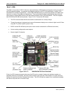
communicates with the user, receives data from and issues commands to a variety of peripheral devices through
the motherboard, the main printed circuit assembly on the rear panel (Figure 3-1).
04521C (DCN5731)