


Operating Instructions Teledyne API - Model 200EH/EM Operation Manual
98
5. If you are adding an analyzer to the end of an already existing chain, don’t forget to remove JP2, pins 21
22 on the multidrop PCA on the analyzer that was previous the last instrument in the chain.
6. Close the instrument.
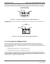
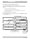
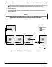
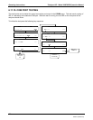
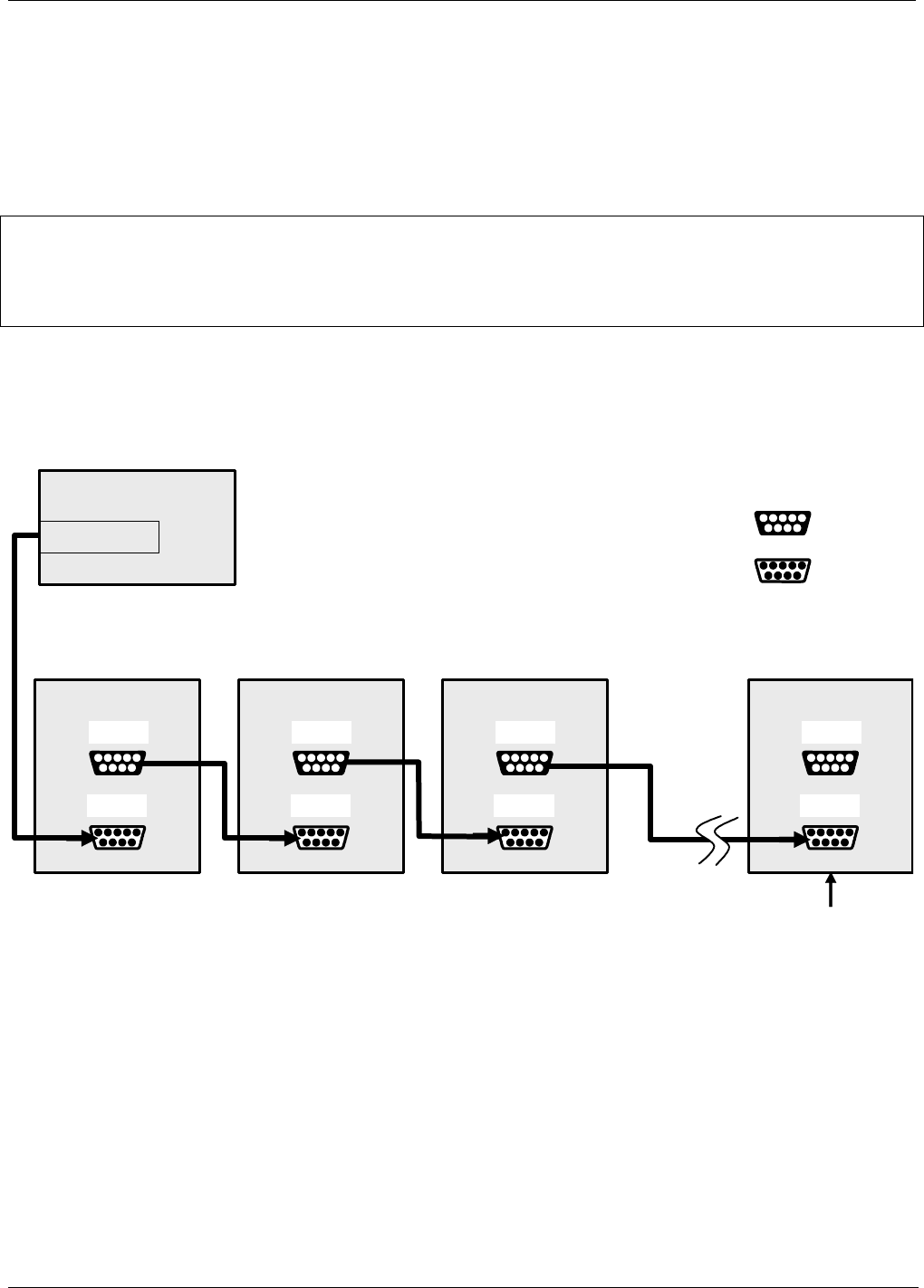
7. Using straight-through, DB9 male DB9 Female cables, interconnect the host and the analyzers as
shown in Figure 6-12.
NOTE:
Teledyne Instruments recommends setting up the first link, between the Host and the
first analyzer and testing it before setting up the rest of the chain.
Analyzer Analyzer Analyzer Last Analyzer
Female DB9
Male DB9
RS-232
COM2
RS-232
COM2
RS-232
COM2
RS-232
COM2
Host
RS-232 port
Make Sure
Jumper between
JP2 pins 21
22
is installed.
KEY:
Figure 6-6-12: RS232-Multidrop PCA Host/Analyzer Interconnect Diagram
04521C (DCN5731)