


Teledyne API - Model 200EH/EM Operation Manual Troubleshooting & Repair
265
11.5.15.3. Ozone Flow
Measure the voltage across TP1 and TP3. With proper ozone flow (250 cm
3
/min), this should be approximately
3.0 ± 0.3 V (this voltage will vary with altitude). With flow stopped (pump turned off), the voltage should be
approximately 0 V. If the voltage is incorrect, the flow sensor or the board may be faulty. A cross-leak to
vacuum inside the Perma Pure dryer may also cause this flow to increase significantly, and the voltage will
increase accordingly. Also, make sure that the gas flows from P1 to P2 as labeled on the flow sensor (“high”
pressure P1 to “low” pressure P2 or “Port” 1 to “Port” 2).
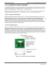
11.5.16. NO
2
CONVERTER
The NO
2
converter assembly can fail in two ways, an electrical failure of the band heater and/or the
thermocouple control circuit and a performance failure of the converter itself.
1) NO
2
converter heater failures can be divided into two possible problems:
Temperature is reported properly but heater does not heat to full temperature. In this case, the heater is
either disconnected or broken or the power relay is broken.
Disconnect the heater cable coming from the relay board and measure the resistance between any
two of the three heater leads with a multi-meter. The resistance between A and B should be about
1000 Ω and that between A and C should be the same as between B and C, about 500 Ω each. If
any of these resistances is near zero or without continuity, the heater is broken.
Temperature reports zero or overload (near 500° C). This indicates a disconnected or failing
thermocouple or a failure of the thermocouple circuit.
First, check that the thermocouple is connected properly and the wire does not show signs of a
broken or kinked pathway. If it appears to be properly connected, disconnect the yellow
thermocouple plug (marked
K) from the relay board and measure the voltage (not resistance)
between the two leads with a multi-meter capable of measuring in the low mV range. The voltage
should be about 12 mV (ignore the sign) at 315° C and about 0 mV at room temperature.
Measure the continuity with an Ohm-meter. It should read close to zero Ω. If the thermocouple does
not have continuity, it is broken. If it reads zero voltage at elevated temperatures, it is broken. To
test the thermocouple at room temperature, heat up the converter can (e.g., with a heat gun) and see
if the voltage across the thermocouple leads changes. If the thermocouple is working properly, the
electronic circuit is broken. In both cases, consult the factory.
2) If the converter appears to have performance problems (conversion efficiency is outside of allowed range of
96-102%), check the following:
Conversion efficiency setting in the CAL menu. If this value is different from 1.000, this correction needs
to be considered. Section 7.1.5 describes this parameter in detail.
Accuracy of NO
2
source (GPT or gas tank standard). NO
2
gas standards are typically certified to only
±2% and often change in concentrations over time. You should get the standard re-certified every year.
If you use GPT, check the accuracy of the ozone source.
Age of the converter. The NO
2
converter has a limited operating life and may need to be replaced every
~3 years or when necessary (e.g., earlier if used with continuously high NO
2
concentrations). We
estimate a lifetime of about 10000 ppm-hours (a cumulative product of the NO
2
concentration times the
exposure time to that concentration). However, this lifetime heavily depends on many factors such as
absolute concentration (temporary or permanent poisoning of the converter is possible), sample flow
rate and pressure inside the converter, converter temperature, duty cycle etc. This lifetime is only an
estimated reference and not a guaranteed lifetime.
04521C (DCN5731)