


Teledyne API - Model 200EH/EM Operation Manual Troubleshooting & Repair
271
11. Adjust the HVPS fine adjustment such that the NORM PMT value is 3600-3700 mV.
The fine adjustment typically increments the
NORM PMT value by about 30 mV.
It may be necessary to go back and forth between coarse and fine adjustments if the proper value is
at the threshold of the min/max coarse setting.
NOTE
Do not overload the PMT by accidentally setting both adjustment switches to their
maximum setting. Start at the lowest setting and increment slowly. Wait 10 seconds
between adjustments.
12. If the NORM PMT value set above is now between 3560-3640 mV, skip this step. Otherwise, adjust the
NORM PMT value with the gain potentiometer down to 3600±10 mV.
his is the final very-fine adjustment.
13. Note that during adjustments, the
NORM PMT value may be fluctuating, as the analyzer continues to
switch between NO and NO
X
streams as well as between measure and AutoZero modes.
You may have to mentally average the values of NO and NO
X
response for this adjustment.
14. Perform a software span calibration (Section 7.2, 7.4, or 7.6) to normalize the sensor response to its
new PMT sensitivity.
15. Review the slope and offse
t values, the slopes should be 1.000±0.300 and the offset values should be
0.0±20 mV (-20 to +150 mV is allowed).
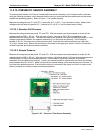
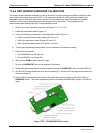
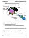
11.6.6. REPLACING THE PMT, HVPS OR TEC
The photo multiplier tube (PMT) should last for the lifetime of the analyzer. However, in some cases, the high
voltage power supply (HVPS) or the thermo-electric cooler (TEC) may fail. In case of PMT, HVPS or TEC
failure, the sensor assembly needs to be opened in order to change one of these components. Refer to Figure
11- for the
structure of the 200EH/EM sensor assembly and follow the steps be
low for replacement of one of its
components. We recommend to ensure that the PMT, HVPS or TEC modules are, indeed, faulty to prevent
unnecessary opening of the sensor.
NOTE
Whereas it is possible for a skilled technician to change the PMT or HVPS through the
front panel with the sensor assembly mounted to the analyzer, we recommend to
remove the entire assembly and carry this procedure out on a clean, anti-static table
with the user wearing an anti-static wrist strap to prevent static discharge damage to
the assembly or its circuits.
1. Power down the analyzer, disconnect the power cord.
2. Remove the cover and disconnect all pneumatic and electrical connections from the sensor assembly.
04521C (DCN5731)