


Teledyne API - Model 200EH/EM Operation Manual Troubleshooting & Repair
261
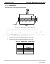
11.5.9.4. Control Inputs
The control input bits can be tested by the following procedure:
Connect a jumper from the +5 V pin on the STATUS connector to the +5 V on the CONTROL IN
connector.
Connect a second jumper from the ‘-‘ pin on the STATUS connector to the A pin on the CONTROL IN
connector. The instrument should switch from
SAMPLE mode to ZERO CAL R mode.
Connect a second jumper from the ‘-‘ pin on the STATUS connector to the B pin on the CONTROL IN
connector. The instrument should switch from
SAMPLE mode to
SPAN CAL R mode.
In each case, the M200EH/EM should return to SAMPLE mode when the jumper is removed.
11.5.10. CPU
There are two major types of CPU board failures, a complete failure and a failure associated with the Disk-On-
Chip (DOC). If either of these failures occur, contact the factory.
For complete failures, assuming that the power supplies are operating properly and the wiring is intact, the CPU
is faulty if on power-on:
The vacuum fluorescence display does not show a dash in the upper left hand corner
There is no activity from the primary RS-232 port (COM1) on the rear panel even if “? <RETURN>” is
pressed.
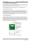
In some rare circumstances, this failure may be caused by a bad IC on the motherboard, specifically U57, the
large, 44 pin device on the lower right hand side of the board. If this is true, removing U57 from its socket will
allow the instrument to start up but the measurements will be incorrect.
If the analyzer stops during initialization (the vacuum fluorescence display shows some text), it is likely
that the DOC, the firmware or the configuration and data files have been corrupted or that the wrong
firmware was uploaded or does not have the correct filename.
04521C (DCN5731)