


Troubleshooting & Repair Teledyne API - Model 200EH/EM Operation Manual
232
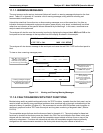
11.1.1. WARNING MESSAGES
The most common and/or serious instrument failures will result in a warning message displayed on the front
panel. Table A-2 in Appendix A.3 contains a list of warning messages, along with their meaning and
recommended corrective action.
It should be noted that if more than two or three warning messages occur at the same time, it is often an
indication that some fundamental analyzer sub-system (power supply, relay board, motherboard) has failed
rather than an indication of the specific failures referenced by the warnings. In this case, a combined-error
analysis needs to be performed.
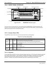
The analyzer will alert the user that a warning is active by displaying the keypad labels
MSG and CLR on the
front panel and a text message in the top center line of the display as shown in this example:
SAMPLE
A
ZERO WARNING NOX =123.4
< TST TST > CAL MSG CLR SETUP
The analyzer will also issue a message to the serial port and cause the red FAULT LED on the front panel to
blink.
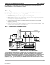
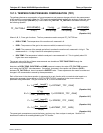
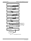
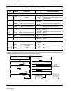
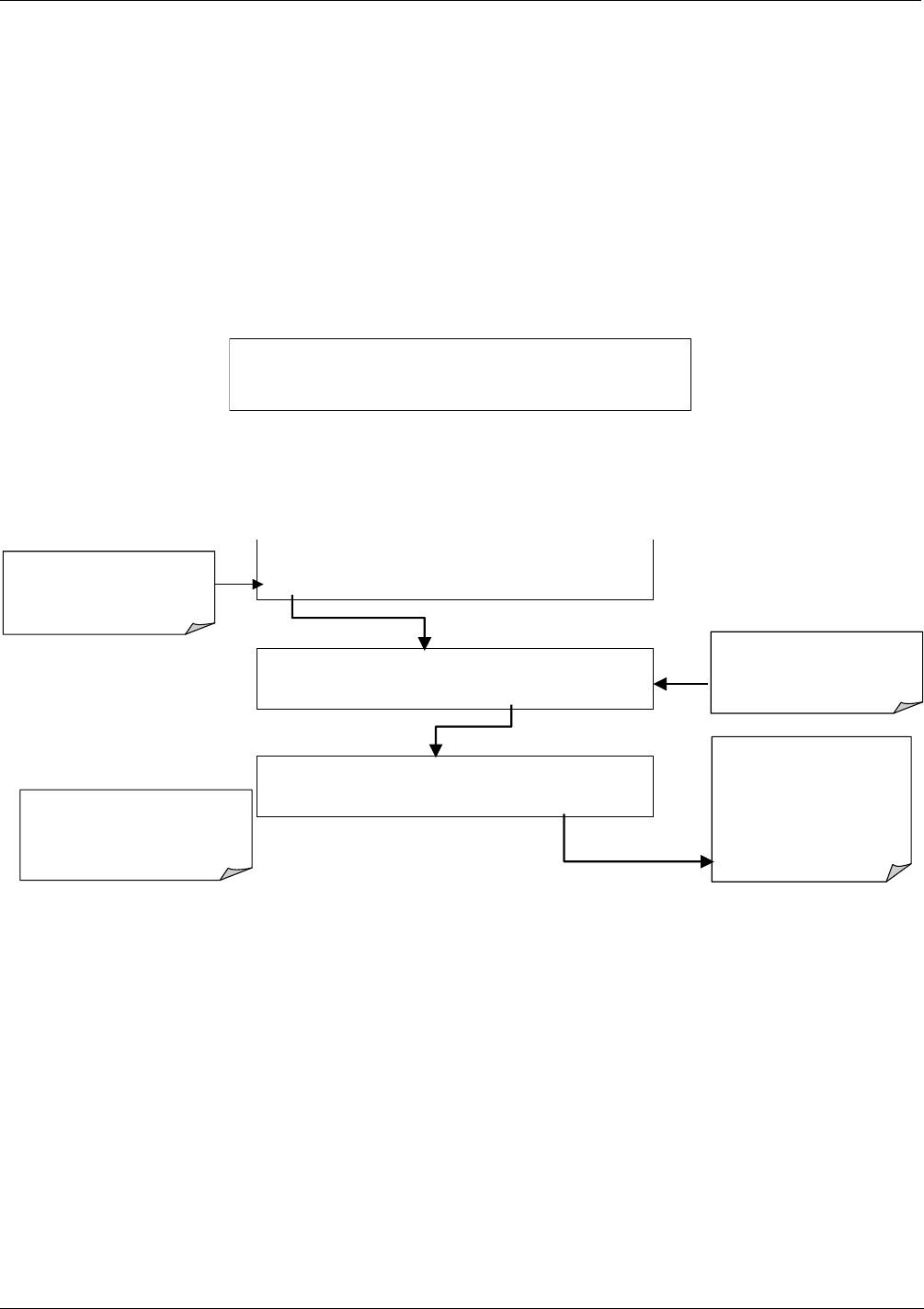
To view or clear a warning messages press:
SAMPLE SYSTEM RESET NOX = XXX.X
TEST CAL MSG CLR SETUP
If warning messages re-appear,
the cause needs to be found. Do
not repeatedly clear warnings
without corrective action.
Press
CLR
to clear the current
warning message.
If more than one warning is
active, the next message will
take its place.
Once the last warning has been
cleared, the analyzer returns to
SAMPLE Mode.
SAMPLE A1:NXCNC1=100PPM NOX=XXX.X
< TST TST > CAL MSG CLR SETUP
SAMPLE SYSTEM RESET NOX = XXX.X
< TST TST > CAL MSG CLR SETUP
<TST TST> keys replaced with
TEST key. Pressing TEST
deactivates warning messages
until new warning(s) are activated.
MSG
indicates that warning
messages are active.
All Warning messages are hidden,
but
MSG
button appears
Figure 11-1: Viewing and Clearing Warning Messages
11.1.2. FAULT DIAGNOSIS WITH TEST FUNCTIONS
Besides being useful as predictive diagnostic tools, the TEST functions, viewable from the front panel, can be
used to isolate and identify many operational problems when combined with a thorough understanding of the
analyzer’s theory of operation (Chapter 10). We recommend to use the APICOM remote control program to
download, g
raph and archive TEST data for analysis
and long-term monitoring of diagnostic data ( Section
6/15.2.8).
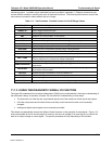
The acceptable ranges for these test functions are listed in Appendix A-3. The actual values for these test
functions on checkout at the factory were also listed in the Final Test and Validation Data Sheet, which was
shipped with the instrument. Values outside the acceptable ranges indicate a failure of one or more of the
analyzer’s subsystems. Functions with values that are within the acceptable range but have significantly
changed from the measurements recorded on the factory data sheet may also indicate a failure or a
04521C (DCN5731)