


Troubleshooting & Repair Teledyne API - Model 200EH/EM Operation Manual
260
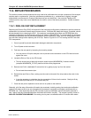
11.5.9.3. Status Outputs
The procedure below can be used to test the Status outputs.
V
+DC Gnd
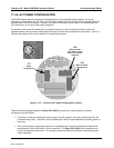
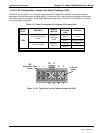
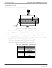
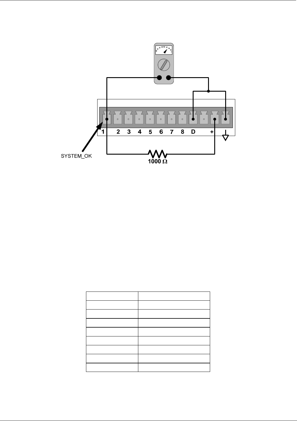
Figure 11-19: Typical Set Up of Status Output Test
1. Connect a cable between the “D“ pin and the “” pin on the status output connector.
2. Connect a 1000 Ω resistor between the “+” pin and the pin for the status output that is being tested.
3. Connect a voltmeter between the “
D“ pin and the pin of the output being tested (Table 11-10).
4. Under the
DIAG / SIGNAL I/O menu (Section 6.13.1), scroll through the inputs and outputs until you get
to the output in question. Alternately turn the output on and off.
The Voltmeter will read approximately 5 VDC when the output is OFF.
The Voltmeter will read approximately 0 VDC when the output is ON.
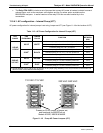
Table 11-10: Status Outputs Pin Assignments
PIN # STATUS
1 SYSTEM OK
2 CONC VALID
3 HIGH RANGE
4 ZERO CAL
5 SPAN CAL
6 DIAG MODE
7 LOW
8 SPARE
04521C (DCN5731)