


Teledyne API - Model 200EH/EM Operation Manual Troubleshooting & Repair
251
11.5. SUBSYSTEM CHECKOUT
The preceding sections of this manual discussed a variety of methods for identifying possible sources of failures
or performance problems within the analyzer. In most cases this included a list of possible causes and, in some
cases, quick solutions or at least a pointer to the appropriate sections describing them. This section describes
how to determine if a certain component or subsystem is actually the cause of the problem being investigated.
11.5.1. SIMPLE VACUUM LEAK AND PUMP CHECK
Leaks are the most common cause of analyzer malfunction; This section presents a simple leak check, whereas
Section 0 details a more thorough procedure. The method described here is easy, fast and detects, but does
not loca
te, most leaks. It also verifies the sample pump condition.
Turn the analyzer ON, and allow at least 30 minutes for flows to stabilize.
Cap the sample inlet port (cap must be wrench-tight).
After several minutes, when the pressures have stabilized, note the SAMP (sample pressure) and the
RCEL (vacuum pressure) readings.
If both readings are equal to within 10% and
less than 10 in-Hg-A, the instrument is free of large leaks.
It is still possible that the instrument has minor leaks.
If both readings are < 10 in-Hg-A, the pump is in good condition. A new pump will create a pressure
reading of about 4 in-Hg-A (at sea level).
11.5.2. DETAILED PRESSURE LEAK CHECK
If a leak cannot be located by the above procedure, obtain a leak checker similar to Teledyne Instruments part
number 01960, which contains a small pump, shut-off valve, and pressure gauge to create both over-pressure
and vacuum. Alternatively, a tank of pressurized gas, with the two stage regulator adjusted to ≤ 15 psi, a shutoff
valve and pressure gauge may be used.
CAUTION
Once tube fittings have been wetted with soap solution under a pressurized system, do
not apply or re-apply vacuum as this will cause soap solution to be sucked into the
instrument, contaminating inside surfaces.
Do not exceed 15 psi when pressurizing the system.
Turn OFF power to the instrument and remove the instrument cover.
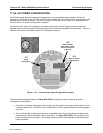
Install a leak checker or a tank of gas (compressed, oil-free air or nitrogen) as described above on the
sample inlet at the rear panel.
Disconnect the pump tubing on the outside rear panel and cap the pump port. If IZS or zero/span valves
are installed, disconnect the tubing from the zero and span gas ports and plug them (Figure 3-2). Cap
the DFU particle filter on the Perma Pure dryer (Figure 9-2).
04521C (DCN5731)