Optional Hardware and Software Teledyne API - Model 200EH/EM Operation Manual
42
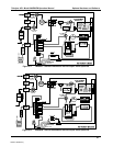
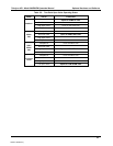
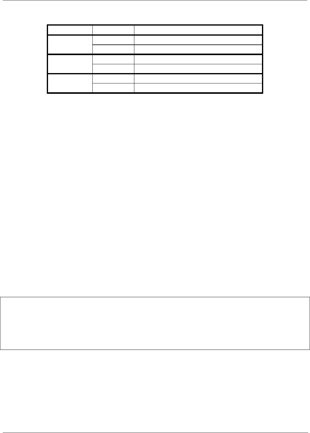
Table 5-1: Zero/Span Valve States
MODE VALVE CONDITION
Sample/Cal Open to sample gas inlet
SAMPLE
Zero/Span Open to zero air inlet
Sample/Cal Open to zero/span inlet (activated)
ZERO
CALIBRATION
Zero/Span Open to zero air inlet
Sample/Cal Open to zero/span inlet (activated)
SPAN
CALIBRATION
Zero/Span Open to span gas inlet / IZS gas (activated)
The state of the zero/span valves can also be controlled:
Manually from the analyzer’s front panel by using the SIGNAL I/O controls located under the DIAG
Menu (Section 6.13.1),
By activating the instrument’s AutoCal feature (Section 7.7),
Remotely by using the external digital control inputs (Section 6.15.1.2) or Ethe
rnet option.
Remotely through the RS-232/485 serial I/O ports (Section 6-11).
All supply lines should be vented outside of the analyzer’s enclosure. In order to prevent back-diffusion and
pressure drop effects, these vent lines should be between 2 and 10 meters in length.
5.7.2. SECOND RANGE SPAN VALVE (OPT 52)
This option includes a special set of valves that allows two separate NO
x
mixtures to enter the analyzer from two
independent sources. Typically these two gas mixtures will come from two, separate, pressurized bottles of
certified calibration gas: one mixed to produce a NO, NO
2
or NO
x
concentration equal to the expected span
calibration value for the application and the other mixed to produce a concentration at or near the midpoint of the
intended measurement range. Individual gas inlets, labeled HIGH SPAN and LOW SPAN are provided at the
back on the analyzer.
The valves allow the user to switch between the two sources via keys on the front panel or from a remote
location by way of either the analyzer’s digital control inputs or by sending commands over it’s serial I/O port(s).
NOTE
The analyzer’s software only allows the SLOPE and OFFSET to be calculated when
sample is being routed through the HIGH SPAN inlet.
The LOW SPAN gas is for midpoint reference checks only.
The state of the optional valves can be controlled:
Manually from the analyzer’s front panel by using the SIGNAL I/O controls located under the DIAG
Menu (Section 6-13.1),
By activating the instrument’s CAL or AutoCal features (Section 7.7),
Remotely by using the external digital control inputs (Section 6.15.1.2) or Ethe
rnet option.
Remotely through the RS-232/485 serial I/O ports (Section 6.11).
04521C (DCN5731)


