


Teledyne API - Model 200EH/EM Operation Manual Calibration Procedures
155
7. CALIBRATION PROCEDURES
This chapter describes calibration procedures for the M200EH/EM. All of the methods described here can be
initiated and controlled through the front panel or the COM ports.
NOTE
CALIBRATION vs. CALIBRATION CHECK
Pressing the ENTR key during the following procedures re-calculates the stored
values for OFFSET and SLOPE and alters the instrument’s calibration.
If you wish to perform a calibration check, DO NOT press the ENTR button.
7.1. CALIBRATION PREPARATIONS
7.1.1. REQUIRED EQUIPMENT, SUPPLIES, AND EXPENDABLES
Calibration of the Model 200EH/EM analyzer requires a certain amount of equipment and supplies. These
include, but are not limited to, the following:
Zero-air source (defined in Section 7.1.2).
Span gas source (defined in Section 7.1.3).
Gas lines - all gas line materials should be stainless steel or Teflon-type (PTFE or FEP). High
concentration NO gas transpo
rted over long distances may require stainless steel to avoid oxidation of
NO with O
2
diffusing into the tubing.
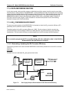
A recording device such as a strip-chart recorder and/or data logger (optional). For electronic
documentation, the internal data acquisition system can be used.
7.1.2. ZERO AIR
Zero air is similar in chemical composition to the Earth’s atmosphere but scrubbed of all components that might
affect the analyzer’s readings. For NO
X
measuring devices, zero air should be devoid of NO
X
and large amounts
of CO
2
, NH
3
and water vapor. Water vapor and moderate amounts of NH
3
can be removed using a sample gas
conditioner (Section 5.10).
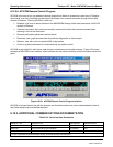
Devices such as the API Model 701 zero air generator that condition ambient air by drying and removal of
pollutants are available. We recommend this type of device for generating zero air. Please contact our sales
department for more information on this.
04521C (DCN5731)