


Teledyne API - Model 200EH/EM Operation Manual Operating Instructions
97
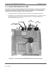
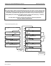
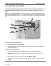
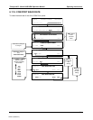
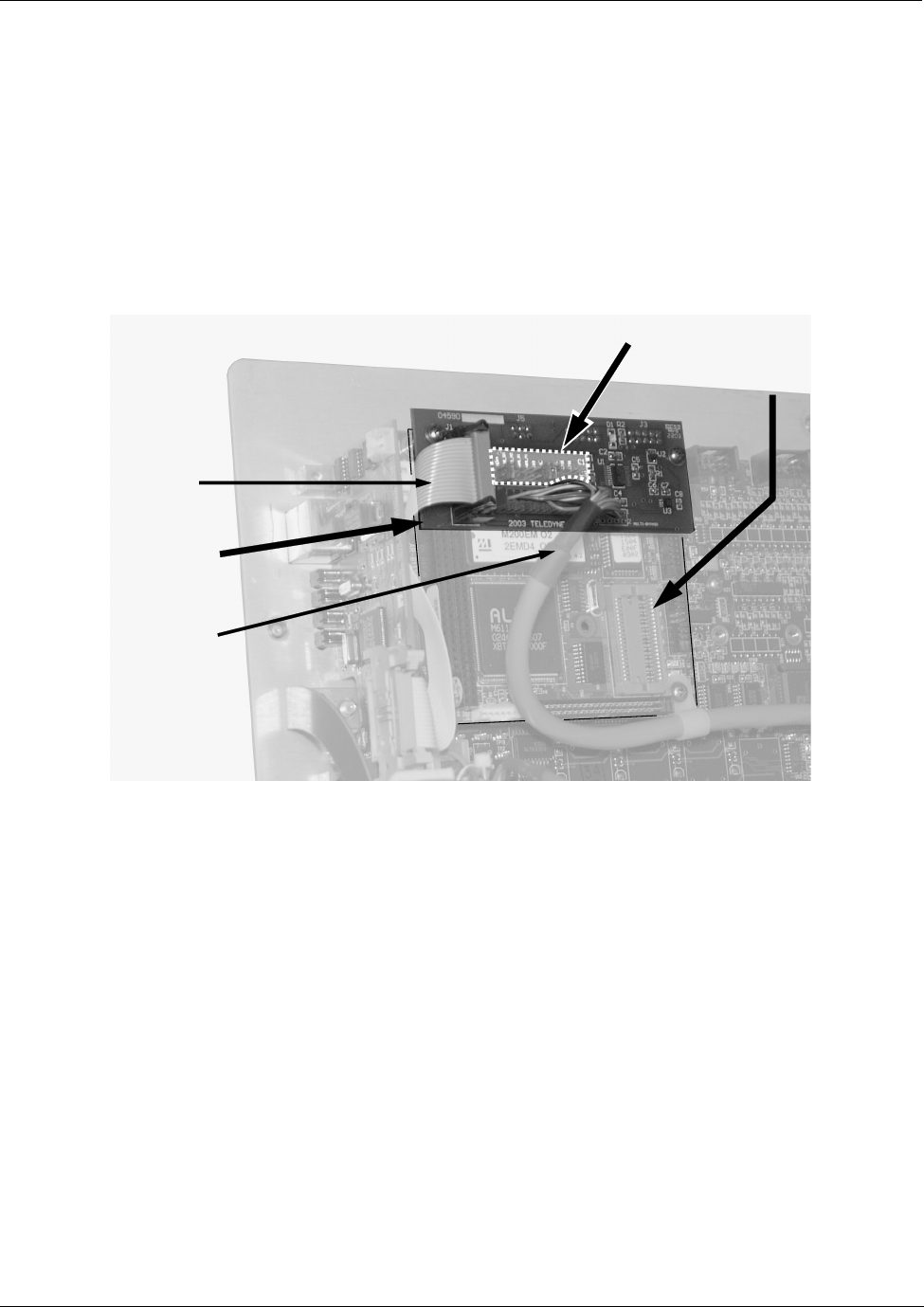
6.11.7. MULTIDROP RS-232 SET UP
The RS-232 multidrop consists of a printed circuit assembly that plugs onto the CN3, CN4, and CN5 connectors
of the CPU card (see Figure 6-11) and the cabling to connect it to the analyzer’s motherboard. This PCA
includes all circuitry required to enable your analyzer for multidrop operation. It converts the instrument’s COM1
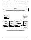
port to multidrop configuration allowing up to eight analyzers to be connected the same I/O port of the host
computer.
Because both of the DB9 connectors on the analyzer’s back panel are needed to construct the multidrop chain,
COM2 is no longer available for separate RS-232 or RS-485 operation, however, with the addition of an Ethernet
Option (option 63, see Sections 5.9.3 and 6.11.6) the COM2 port is available for communication over a 10BaseT
LAN.
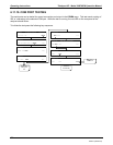
Rear Panel
(as seen from inside)
CPU Card
Multidrop
PCA
JP2
Cable to
Ethernet
Card
Cable to
Motherboard
Figure 6-6-11: Location of JP2 on RS232-Multidrop PCA (option 62)
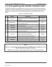
Each analyzer in the multidrop chain must have:
One Teledyne Instruments option 62 installed.
One 6’ straight-through, DB9 male DB9 Female cable (Teledyne Instruments P/N WR0000101) is
required for each analyzer.
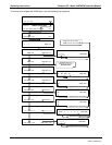
To set up the network, for each analyzer:
1. Turn the analyzer on and change its ID code (see Section 6.11.1) to a unique 4-digit number.
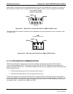
2. Remove the top cover (see Section 3.1) of the analyzer and locate JP2 on the multidrop PCA (see
Figure 6-11)
3. Make sure that the jumpers are in place connection pins 9
10 and 11 12.
4. If the analyzer is to be the last instrument on the chain, make sure a jumper is in place connecting pins
21
22.
04521C (DCN5731)