


Teledyne API - Model 200EH/EM Operation Manual Operating Instructions
135
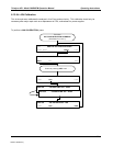
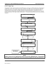
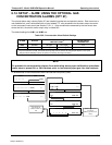
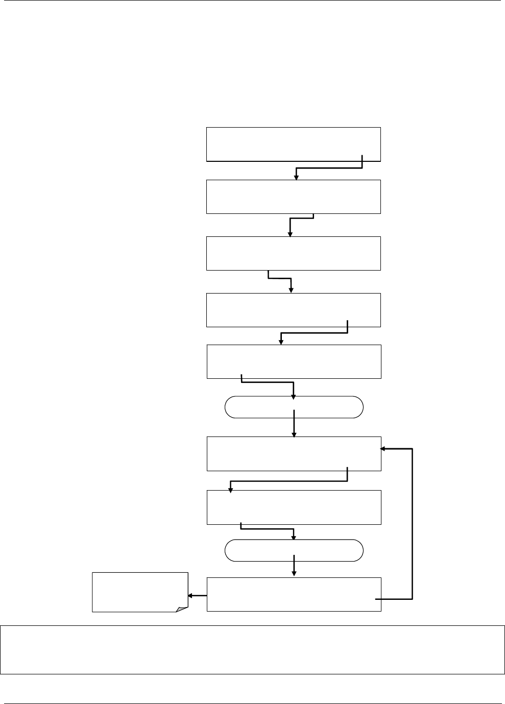
6.13.7.2. Optic Test
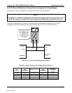
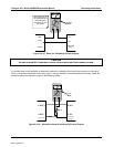
The optic test function tests the response of the PMT sensor by turning on an LED located in the cooling block of
the PMT (Fig. 10-15). The analyzer uses the light emitted from the LED to test its photo-electronic subsystem,
including the PMT and the current to voltage converter on the pre-amplifier board. To make sure that the
analyzer measures only the light coming from the LED, the analyzer should be supplied with zero air. The optic
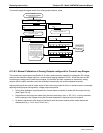
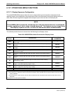
test should produce a PMT signal of about 2000±1000 mV. To activate the electrical test press the following key
sequence.
SAMPLE RANGE = 500.0 PPB NOX=X.X
< TST TST > CAL SETUP
SETUP X.X
PRIMARY SETUP MENU
CFG DAS RNGE PASS CLK MORE EXIT
SETUP X.X
SECONDARY SETUP MENU
COMM VARS DIAG ALRM EXIT
DIAG SIGNAL I / O
PREV NEXT JUMP ENTR EXIT
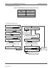
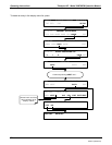
DIAG OPTIC A1:NXCNC1=100PPM NOX=XXX.
X
<TST TST> EXIT
SETUP X.X ENTER DIAG PASS: 818
8 1 8 ENTR EXIT
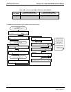
Press NEXT until…
DIAG OPTIC TEST
PREV NEXT ENTR EXIT
Press TST until…
DIAG ELEC PMT = 2751 MV NOX=X.X
<TST TST> EXIT
While the optic test is
activated, PMT should be
2000 mV ± 1000 mV
NOTE
This is a coarse test for functionality and not an accurate calibration tool. The resulting
PMT signal can vary significantly over time and also changes with low-level calibration.
04521C (DCN5731)