


Troubleshooting & Repair Teledyne API - Model 200EH/EM Operation Manual
252
Pressurize the instrument with the leak checker or tank gas, allowing enough time to fully pressurize the
instrument through the critical flow orifice. Check each tube connection (fittings, hose clamps) with soap
bubble solution, looking for fine bubbles. Once the fittings have been wetted with soap solution, do not
re-apply vacuum as it will draw soap solution into the instrument and contaminate it. Do not exceed 15
psi pressure.
If the instrument has the zero and span valve option, the normally closed ports on each valve should
also be separately checked. Connect the leak checker to the normally closed ports and check with soap
bubble solution.
If the analyzer is equipped with an IZS Option Connect the leak checker to the Dry Air inlet and check
with soap bubble solution.
Once the leak has been located and repaired, the leak-down rate of the indicated pressure should be
less than 1 in-Hg-A (0.4 psi) in 5 minutes after the pressure is turned off.
Clean surfaces from soap solution, re-connect the sample and pump lines and replace the instrument
cover. Restart the analyzer.
11.5.3. PERFORMING A SAMPLE FLOW CHECK
CAUTION
Use a separate, calibrated flow meter capable of measuring flows between 0 and 1000
cm³/min to measure the gas flow rate though the analyzer. Do not use the built in flow
measurement viewable from the front panel of the instrument. This value is only
calculated, not measured.
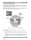
Sample flow checks are useful for monitoring the actual flow of the instrument, as the front panel display shows
only a calculated value. A decreasing, actual sample flow may point to slowly clogging pneumatic paths, most
likely critical flow orifices or sintered filters. To perform a sample flow check:
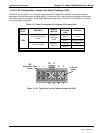
Disconnect the sample inlet tubing from the rear panel SAMPLE port shown in Figure 3-2.
Attach the outlet port of a flow meter to the sample inl
et port on the rear panel. Ensure that the inlet to
the flow meter is at atmospheric pressure.
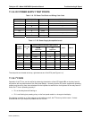
The sample flow measured with the external flow meter should be within 10% of the nominal values
shown in Table 10-3.
Low flows indicate blockage somewhere in the pneumatic pathway. ]
04521C (DCN5731)