Teledyne API - Model 200EH/EM Operation Manual Theory of Operation
197
10.3.3. FLOW RATE CONTROL - CRITICAL FLOW ORIFICES
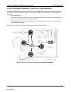
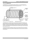
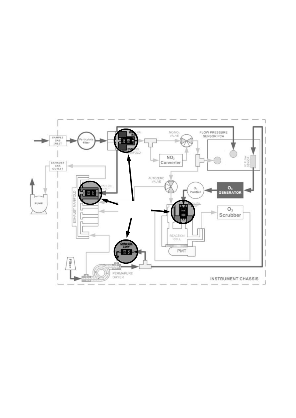
The Model M200EH/EM analyzers use special flow control assemblies located at various locations around the
instrument to maintain constant flow rates for both the O
3
supply air and the sample gas. These assemblies
consists of:
A critical flow orifice.
Two o-rings: Located just before and after the critical flow orifice, the o-rings seal the gap between the
walls of assembly housing and the critical flow orifice.
A spring: Applies mechanical force needed to form the seal between the o-rings, the critical flow orifice
and the assembly housing.
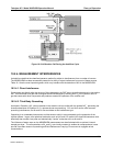
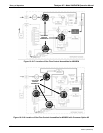
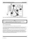
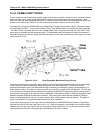
See Figures 10-6 through 10-9 For the location of these flow control assemblies:
GAS FLOW
CONTROL
ASSEMBLIES
SAMPLE
PRESSURE
SENSOR
VACUUM
PRESSURE
SENSOR
Figure 10-10-6: Location of Gas Flow Control Assemblies for M200EH
04521C (DCN5731)


