


Theory of Operation Teledyne API - Model 200EH/EM Operation Manual
224
10.6.1. FRONT PANEL INTERFACE
POWER
FAULT
CAL
SAMPLE
CHEMILUMINESENCE NO
x
ANALYZER – M200EH
????????????????????????????????????????
MODE FIELD
KEY
DEFINITIONS
MESSAGE FIELD CONCENTRATION FIELD
STATUS
LED’s
KEYBOARD
ON / OFF
SWITCH
FASTENERFASTENER
HINGE
SAMPLE A1:NXCNC1=100PPM NOX=XXX.X
< TST TST > CAL SETUP
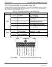
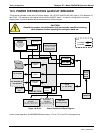
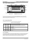
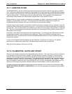
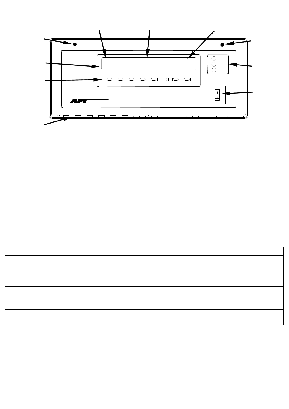
Figure 10-10-27: M200EH/EM Front Panel Layout
The most commonly used method for communicating with the M200EH/EM UV Chemiluminescence NO
x
Analyzer is via the instrument’s front panel which includes a set of three status LEDs, a vacuum florescent
display and a keyboard with 8 context sensitive keys.
10.6.1.1. Analyzer Status LED’s
Three LEDS are used to inform the user of the instruments basic operating status
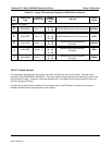
Table 10-6: Front Panel Status LED’s
NAME COLOR STATE DEFINITION
SAMPLE Green
Off
On
Blinking
Unit is not operating in sample mode, iDAS is disabled.
Sample Mode active; Front Panel Display being updated, iDAS data being stored.
Unit is operating in sample mode, front panel display being updated, iDAS hold-off mode is
ON, iDAS disabled
CAL Yellow
Off
On
Blinking
Auto Cal disabled
Auto Cal enabled
Unit is in calibration mode
FAULT Red
Off
Blinking
No warnings exist
Warnings exist
10.6.1.2. Keyboard
A row of eight keys just below the vacuum florescent display (see Figure 10-27) is the main method by which the
user interacts with the analyzer. As the software is operated, labels appear on the bottom row of the display
directly above each active key, defining the function of that key as it is relevant for the operation being
performed. Pressing a key causes the associated instruction to be performed by the analyzer.
04521C (DCN5731)