


Teledyne API - Model 200EH/EM Operation Manual Troubleshooting & Repair
257
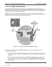
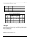
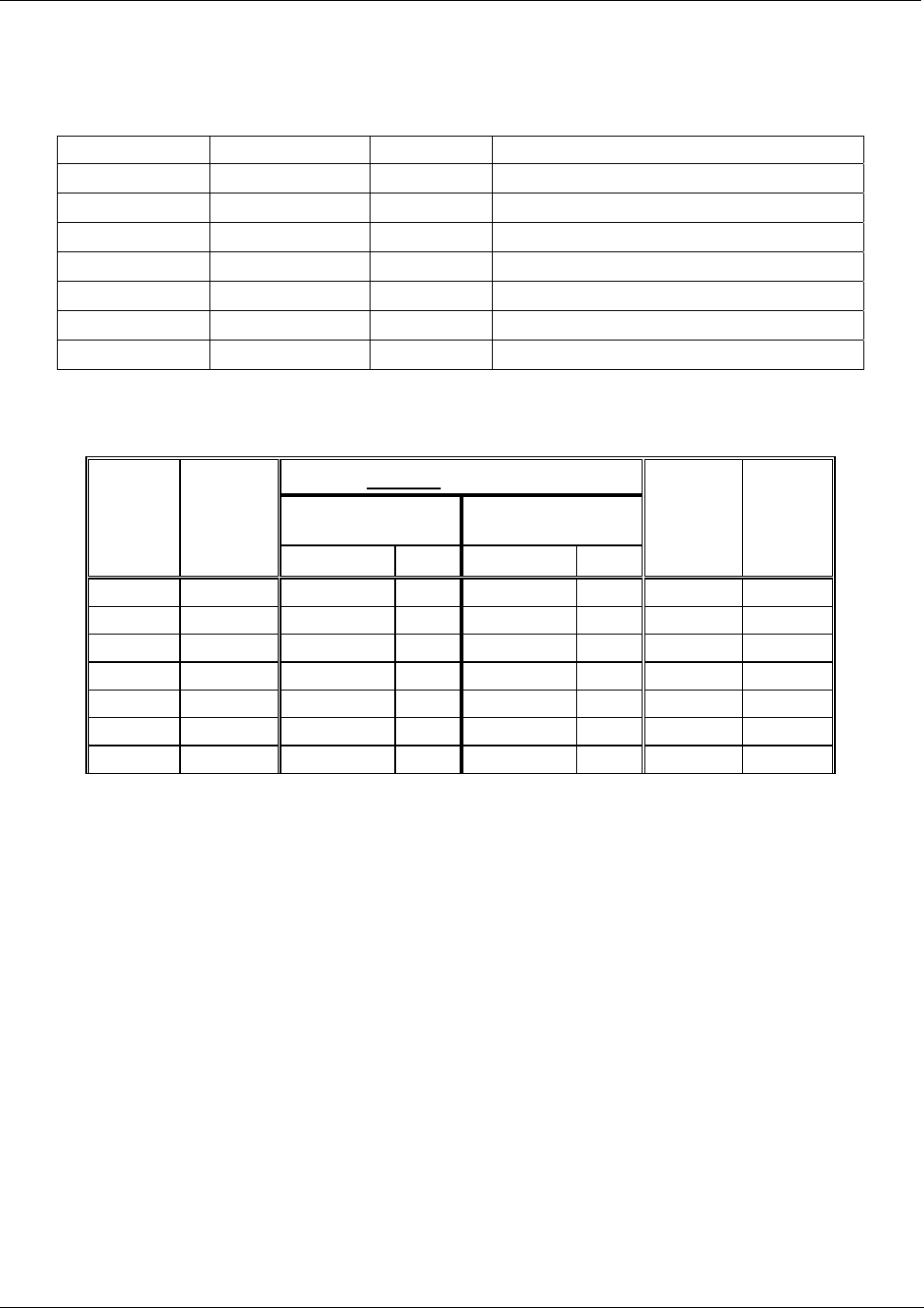
11.5.5. DC POWER SUPPLY TEST POINTS
Table 11-6: DC Power Test Point and Wiring Color Code
NAME TEST POINT# COLOR DEFINITION
DGND
1
Black Digital ground
+5V
2
Red
AGND
3
Green Analog ground
+15V
4
Blue
-15V
5
Yellow
+12R
6
Purple 12 V return (ground) line
+12V
7
Orange
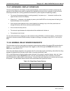
Table 11-7: DC Power Supply Acceptable Levels
CHECK RELAY BOARD TEST POINTS
FROM
Test Point
TO
Test Point
POWER
SUPPLY
VOLTAG
E
NAME # NAME #
MIN V MAX V
PS1 +5 DGND 1 +5 2 +4.80 +5.25
PS1 +15 AGND 3 +15 4 +13.5 +16.0
PS1 -15 AGND 3 -15V 5 -14.0 -16.0
PS1 AGND AGND 3 DGND 1 -0.05 +0.05
PS1 Chassis DGND 1 Chassis N/A -0.05 +0.05
PS2 +12 +12V Ret 6 +12V 7 +11.8 +12.5
PS2 DGND +12V Ret 6 DGND 1 -0.05 +0.05
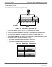
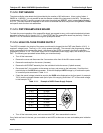
The test points are located at the top, right-hand corner of the PCA (see Figure 11-4)
11.5.6. I
2
C BUS
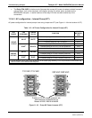
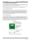
Operation of the I
2
C bus can be verified by observing the behavior of the LED labeled D1 on the relay board in
conjunction with the performance of the front panel display. Assuming that the DC power supplies are operating
properly and the wiring from the motherboard to the keyboard as well as from the keyboard to the relay board is
intact, the I
2
C bus is operating properly if:
D1 on the relay board is flashing or
D1 is not flashing but pressing a key on the front panel results in a change to the display.
If the display is locked up or if the analyzer is not booting up at all, the I
2
C bus may be the cause. Contact
customer service if you suspect a problem with the I
2
C bus.
04521C (DCN5731)