


Chapter 1 SU700 Components, Connections, and Startup 21
CHAPTER 1
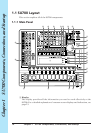
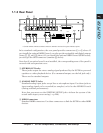
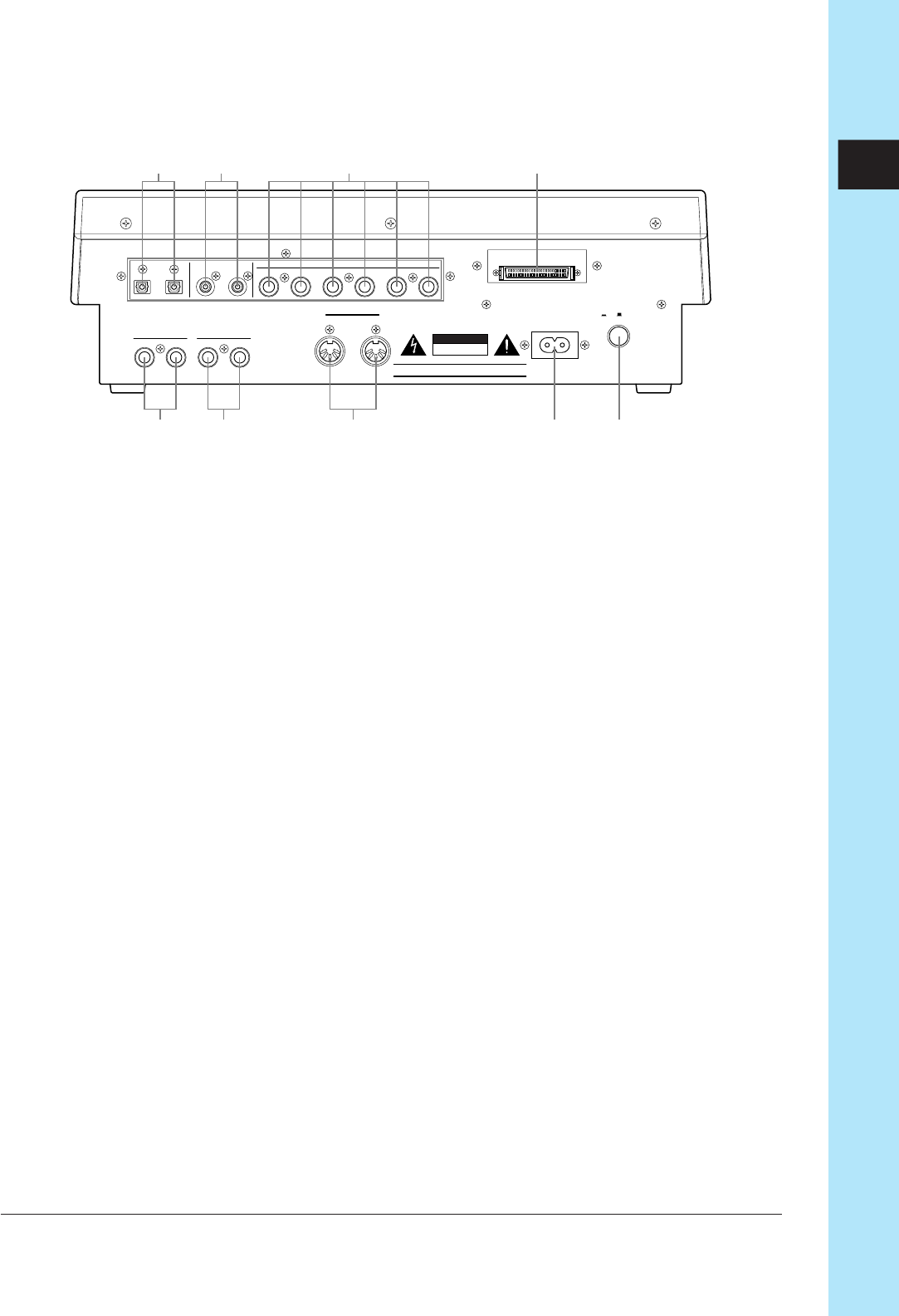
1.1.3 Rear Panel
R L/MONO
STEREO OUT
R L
ANALOG INPUT
AS2 AS1AS3AS4AS5AS6OUTIN
OUTIN
ASSIGNABLE OUTDIGITALOPTICAL
AC INLET
OUT IN
MIDI
POWER
ON/ OFF
ATTENTION :RISQUE DE CHOC ELECTRIQUE ME PAS OUVRIR.
RISK OF ERECTRIC SHOCK
DO NOT OPEN
WARNING
TO REDUCE THE RISK OF FIRE OR ERECTRIC SHOCK
DO NOT EXPOSE THIS PRODUCT TO RAIN OR MOISTURE.
CAUTION
SCSI
1
2
345
9
67 8
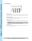
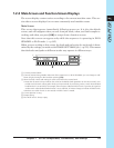
∗ Circled numbers indicate standard connectors. Numbers enclosed in squares indicate options.
In its standard configuration, the rear panel provides connectors 1 to 5 above. If
you install the optional AIEB1 board, you also get the assignable and digital outputs
(items 7, 8, and, 9 above). If you install the optional ASIB1 board (SCSI board),
you also get the SCSI connector (number 6 above).
Note that if an option board is not installed, the corresponding area of the panel is
covered with an expansion cover.
1 STEREO OUT Jacks
These jacks output the stereo analog signal produced by the SU700 to powered
speakers or other playback device. (For monaural output, use the left jack only.)
These are the standard outputs.
2 ANALOG INPUT Jacks
Standard analog input jacks accept line or microphone input. Use these jacks to
input analog signals to be recorded (as samples) or fed to the AUDIO IN track
(during realtime performance).
Note that you must use the SYSTEM | SETUP job to inform the system of the
actual audio input you are using (→ p.298).
3 MIDI Connectors
Standard MIDI connectors. Use these connectors to link the SU700 to other MIDI
devices.