


Chapter 1
SU700 Components, Connections, and Startup
22 Chapter 1 SU700 Components, Connections, and Startup
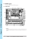
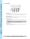
4 AC Inlet
Connects to SU700 power cord.
CAUTION
Use the supplied power cord only. Use of a different cord may result in electric shock or
device damage.
5 POWER Switch
Switches the SU700 power ON and OFF.
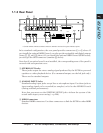
<If AEIB1 option board is installed>
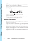
6 OPTICAL IN/OUT connectors
7 DIGITAL IN/OUT connectors
Use the OPTICAL connectors to input or output digital audio signals over optical-
fiber cable. Use the DIGITAL connectors to input or output digital audio signals
over coaxial (RCA-pin) cable, in CD/DAT (S/P DIF) format.
Each connector can support both mono and stereo signals.
Input Signal: The SU700 can accept input digital frequencies of 11.025kHz,
22.05kHz, 32.0kHz, 44.1kHz, and 48.0kHz. (If you wish to enable
this input, you must open the SYSTEM | SETUP job and set AU-
DIO IN to either OPTICAL or DIGITAL. See page 302.)
Output Signal: The output frequency is always 44.1kHz. The output is the digital
equivalent of the signal directed to the STEREO OUT jacks, but
is not passed through the effects blocks. Note that the OPTICAL
OUT and DIGITAL OUT connectors will always produce the iden-
tical signal.
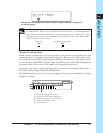
8 ASSIGNABLE analog output jacks
You can set the output destination independently for each nonempty sample
track. Settings can be entered separately for each song. Note that these settings
are not available for the AUDIO IN track, for the MASTER TRACK, and for
sample tracks that do not currently contain a sample.
Under default conditions, output is directed to the STEREO OUT jacks (and OP-
TICAL and DIGITAL connectors). As an alternative, however, you can use the
TRACK SET | SETUP job to direct the track’s output to any one of the assignable
outputs (AS 1 to AS 6), or to an adjacent pair of outputs (AS 1+2, AS 3+4, or AS
5+6). Note that signals directed to assignable outputs do not pass through the ef-
fects blocks (do not receive any effects).
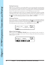
<If ASIB1 option board is installed>
9 SCSI connector
A SCSI-2 D-sub half-pitch 50-pin connector that can be used to connect to an ex-
ternal SCSI disk device. Allows for convenient saving and loading of large quanti-
ties of data.