


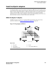

1Install and cable a G600 cabinet
Connect external alarms and auxiliary connections
S8100 Installation and Upgrades 113
November 2003
Connect external alarms and auxiliary connections
NOTE:
The AUX connector is part of the Processor Interface cable assembly (J1). When the
wiring and administration are complete, give these wiring records to the Customer System
Administrator for troubleshooting purposes.
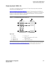
Alarm input
Alarms can be generated on adjunct equipment, sent to the S8100 system, and recorded and reported as
“external alarms.”
CAUTION:
Pins 26 and 1 on the AUX connector are dedicated to the UPS alarm input. Using these
pins for other alarm inputs will cause the S8100 system to reset.
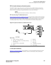
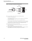
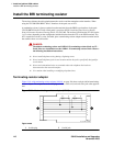
1 Connect 1 major alarm input wire pair and 1 minor alarm input wire pair to the auxiliary field
from the AUX connector (J1 on Processor Interface cable). See Table 14, Alarm inputs at AUX
connector, on page 113 and Figure 33, UPS connection to G600 or CMC1, on page 114.
Alarm output
The system provides a relay contact closure that can operate a customer-provided alarm, such as a light or
bell. The customer provides the circuitry and power source. The alarm device must not exceed a rating of
more than 30 VAC RMS or 60 VDC at 0.75 Amps.
To connect alarm output:
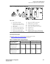
1 Connect the external alarm output. See Table 15, Alarm output at AUX connector, on page 114.
2 Type change system-parameters maintenance and press .
3 Change the CPE Alarm Activation Level field to the desired alarm level and press .
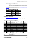
Table 14: Alarm inputs at AUX connector
Alarm input type Color AUX connector
Major (UPS) White-Blue AP2 (Pin 27)
Blue-White Ground (Pin 2)
Minor White-Orange AP2 (Pin 26)
Orange-White Ground (Pin 1)
ENTER
ENTER