


1Install and cable a G600 cabinet
Install emergency-transfer panel and associated telephones
S8100 Installation and Upgrades 129
November 2003
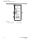
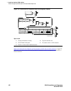
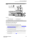
3 Locate the circuit start selection switches (the 1
st
10 2-position switches on the left side of the
808A. See Figure 42, 808A emergency-transfer panel,
on page 128.) These switches set each of
the 5 incoming trunk lines to either loop start or ground start. Two switches are used for each of
the 5 circuits; switches 1 and 2 are used for circuit 1, switches 3 and 4 are used for circuit 2, and
so forth. See Table 20, Trunk/test switches,
on page 129.
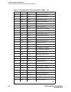
4 Connect a 25-pair cable between the male RJ21 25-pair connector on the 808A and the yellow
field on the MDF. Table 21, Pin assignments for 25-pair connector on 808A,
on page 130 shows
the pinouts.
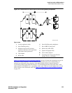
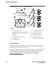
5 Make cross-connections for each emergency trunk/emergency station pair. See Figure 43,
Connections for telephone used for emergency transfer, on page 132 and Figure 44, Connections
for telephone used for emergency transfer and as normal extension, on page 133.
6 On the trunk identification label at the bottom of the panel, record the trunk line, extension, and
location for each circuit.
7 To each voice terminal designated as an emergency terminal, attach a label identifying it as such.
The labels are provided with the unit.
8 Check the system for normal operation as follows:
a Place the test switch (switch 12) in NORMAL OPERATION.
b Ensure the power supply is providing -48 VDC at 80 mA maximum. The power LED
should be ON.
c Check wiring connections.
d Verify that there is dial tone on every emergency transfer set.
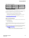
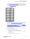
Table 20: Trunk/test switches
Switch
number
Circuit
number
11
21
32
42
53
63
74
84
95
10 5
11 Not used
12 Test switch