


A Cable pinouts
Connector and cable diagrams – pinout charts
274 S8100 Installation and Upgrades
November 2003
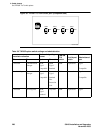
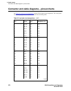
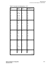
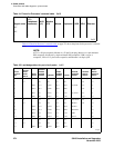
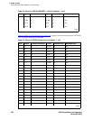
Table 41, Pinout for Processor’s external cable, on page 272 shows the pinout for the processor’s external
cable.
NOTE:
AUX is a 50-pin receptacle, Modem is a 25-pin D-sub plug, Mouse is a 6-pin miniature
DIN receptacle, Keyboard is a 6-pin miniature DIN receptacle, USB is a type A
receptacle, VGA is a 15-pin D-sub receptacle, and Ethernet is an 8-pin jack.
NC –
NC –
–1
Table 41: Pinout for Processor’s external cable 3 of 3
Signal name
Processor
(P1)
(amphenol
connector)
AUX
(J1)
Modem
(P2) Mouse Keyboard USB VGA Ethernet
3 of 3
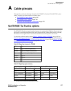
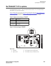
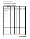
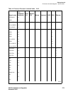
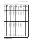
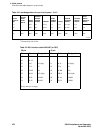
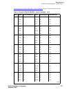
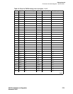
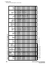
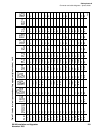
Table 42: Lead designations for port circuit packs 1 of 3
Cross-
connect
pin
TN742/B
TN747B
TN753
TN769
TN2147
TN754
TN726
TN760/B
TN760C
TN760D
TN2209 TN762/B
TN763
TN763B
TN763C TN735
TN767B
TN464GP
TN2207
TN746/B
TN2183
TN2215
TN793
TN2793
TN2224/B
TN2214
1 T.1 T.1 T.1 T.1 T.1 C_5 T.1 T.1
2 R.1 R.1 R.1 R.1 R.1 R.1 R.1
3 TXT.1 T1.1 TXT.1 SZ.1 BT.1 C_ENAB T.2 T.2
4 TXR.1 R1.1 TXR.1 SZ1.1 BR.1 R.2 R.2
5 PXT.1 E.1 PXT.1 S.1 LT.1 C_SYNC* T.3 T.3
6 PXR.1 M.1 PXR.1 S1.1 LR.1 R.3 R.3
7 T.2 T.2 T.2 T.2 T.2 C2D-DATA T.4 T.4
8 R.2 R.2 R.2 R.2 R.2 RDATA* R.4 R.4
9 TXT.2 T1.2 TXT.2 SZ.2 BT.2 TDATA* T.5
10 TXR.2 R1.2 TXR.2 SZ1.2 BR.2 TRSYSNC R.5
11 PXT.2 E.2 PXT.2 S.2 LT.2 GRD T.6
12 PXR.2 M.2 PXR.2 S1.2 LR.2 SCLK* R.6
13 T.3 T.3 T.3 T.3 T.3 T.7
14 R.3 R.3 R.3 R.3 R.3 R.7
15 TXT.3 T1.3 TXT.3 SZ.3 BT.3 T.8
1 of 3