


A Cable pinouts
Connector and cable diagrams – pinout charts
278 S8100 Installation and Upgrades
November 2003
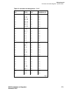
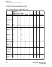
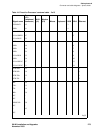
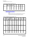
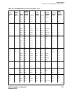
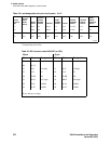
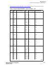
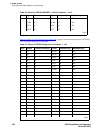
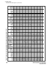
Table 45, Pinout for TN793 Analog Line circuit pack, on page 278 shows the pinout for the TN793 and
TN2793 24-port Analog Line circuit pack.
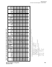
8 TXT.8 29 BK-SL 40 304
TXR.8 30 SL-BK 15 204
PXT.8 31 Y-BL 41 305
PXR.8 32 BL-Y 16 205
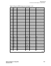
Table 45: Pinout for TN793 Analog Line circuit pack 1 of 2
Port Signal Cross-connect pin Color Amphenol pin Backplane pin
1T.1 1 W-BL26 102
R.1 2 BL-W 01 002
2 T.2 3 W-O 27 103
R.2 4 O-W 02 003
3 T.3 5 W-G 28 104
R.3 6 G-W 03 004
4T.4 7 W-BR29 105
R.4 8 BR-W 04 005
5T.5 9 W-SL30 106
R.5 10 SL-W 05 006
6 T.6 11 R-BL 31 107
R.6 12 BL-R 06 007
7 T.7 13 R-O 32 108
R.7 14 O-R 07 008
8 T.8 15 R-G 33 109
R.8 16 G-R 08 009
9 T.9 17 R-BR 34 110
R.9 18 BR-R 09 010
10 T.10 19 R-SL 35 111
R.10 20 SL-R 10 011
11 T.11 21 BK-BL 36 112
R.11 22 BL-BK 11 012
1 of 2
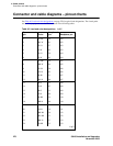
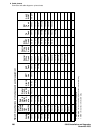
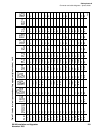
Table 44: Pinout for TN2185 ISDN-BRI – 4-Wire S interface 2 of 2
Port Signal Cross-connect pin Color Amphenol pin Backplane pin
2 of 2