


1Install and cable a G600 cabinet
Install emergency-transfer panel and associated telephones
S8100 Installation and Upgrades 133
November 2003
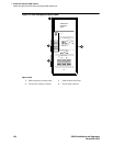
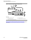
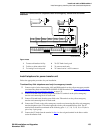
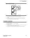
Figure 44: Connections for telephone used for emergency transfer and as normal
extension
Install telephone for power-transfer unit
Follow the appropriate procedure for your installation.
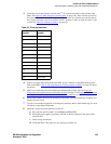
Trunk/auxiliary field: telephone used only for emergency transfer
1 Connect a pair of wires between the -48V and GRD terminals on the yellow emergency transfer
row/connecting block and the EM TRANS RELAY PWR terminal. See Figure 43, Connections
for telephone used for emergency transfer, on page 132.
2 Connect CO trunk leads from the purple field to the TC terminals on the yellow emergency
transfer row/connecting block for each trunk.
3 Connect CO trunk leads from the green field to the TK terminals on the yellow emergency
transfer row/connecting block for each trunk.
4 Connect the ST leads on the yellow emergency transfer row/connecting block for each emergency
transfer telephone to the ST terminal appearance in the yellow trunk/auxiliary field. The ST
terminal leads should be terminated on the following pairs: 1, 4, 7, 10, 13, 16, 19, or 22 (the 1
st
pair of any 3-pair group).
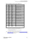
5 Connect the ST leads from the terminal in Step 4 to the assigned terminal in the blue or white
station distribution field.
Figure notes
1 To network interface facility
2 To blue or white station field
3 To Analog Line circuit pack
4 To CO Trunk circuit pack
5 To power-transfer unit
6 To control carrier’s AUX connector
TC TK LC ST
1M 1m 2M 2m 3M
ALARM MONITORS EM TRANS RELAY PWR ACC PWR
3m 3w
TC TK LC ST TC TK LC ST TC TK LC ST TC TK LC ST
C
O
M
1
N
O
1
N
C
2
N
C
1
C
O
M
2
N
O
2
C
O
M
3
N
C
3
G
R
D
-48
V
2820
10
35
EMXR
ST
ST
7
5 76 83 4
r758582b MMR 042996