ELED boot sequence/ TN2314 Processor
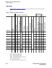
LED boot sequence
S8100 Installation and Upgrades 323
November 2003
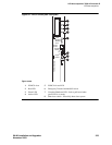
Figure 52: TN2314 circuit pack’s faceplate
Figure notes
1 PCMCIA slots
2 Red LED
3 Green LED
4 Amber LED
5 PCMCIA in-use LED
6 Emergency Transfer On/Auto/Off switch
7 Complete Shutdown LED – Safe to pull board when
green LED is on steady
8 Shut-down switch – Gracefully shuts down system
Do Not Remove Board Unitl
Shutdown Is Complete
On
Auto
Off
In Use
Do Not Remo
ve
Maj Alarm
Min Alarm
Clock
Service
Access
Emergency
Transfer
Complete
Shutdown
6
7
8
3
4
Do Not RemoveWhen In Use
1
2
5


