


S8100 Installation and Upgrades 267
November 2003
Cable pinouts
Set TN760E Tie Trunk’s options
A
A Cable pinouts
This appendix provides the following information for TN760E Tie Trunk and TN464GP T1/E1 option
settings, connector and cable diagrams, and pinout charts.
• Set TN760E Tie Trunk’s options on page 267
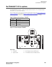
• Set TN464GP T1/E1’s options on page 269
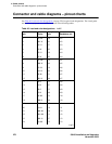
• Connector and cable diagrams – pinout charts on page 270
Set TN760E Tie Trunk’s options
The TN760E Tie Trunk circuit pack interfaces between 4 tie trunks and the TDM bus. Two tip and ring
pairs form a 4-wire analog transmission line. An E & M pair are DC signaling leads used for call setup.
The E-lead receives signals from the tie trunk and the M-lead transmits signals to the tie trunk.
To choose the preferred signaling format (Table 36, Signaling formats for TN760E,
on page 267 and
Table 37, Signaling type summary,
on page 267), set the switches on the TN760E and administer the port
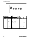
using Figure 50, TN760D Tie Trunk circuit pack (component side),
on page 268 and Table 38, TN760E
option-switch settings and administration, on page 268.
Table 36: Signaling formats for TN760E
Mode Type
E & M Type I Standard (unprotected)
E & M Type I Compatible (unprotected)
Protected Type I Compatible, Type I Standard
Simplex Type V
E & M Type V
E & M Type V Revised
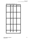
Table 37: Signaling type summary
Signaling type Transmit (M-lead) Receive (E-lead)
On-hook Off-hook On-hook Off-hook
Type I Standard ground battery open
1
/battery
1 An open circuit is preferred instead of battery voltage.
ground
Type I Compatible open
1
/battery ground ground open
1
/battery
Type V open
1
/battery ground open ground
Type V Reversed ground open ground open