


1 Install and cable a G600 cabinet
Install equipment-room hardware for G600
86 S8100 Installation and Upgrades
November 2003
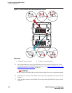
1 Securely mount the external modem at the left of the modem utility shelf or another secure
surface.
2 Route the modem cable (P2) from the Processor Interface cable to the modem and attach it to the
modem port.
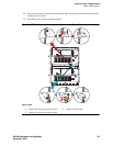
3 Plug the modem power cord into the same power source as the G600(s), preferably the UPS.
4 Connect the modem to a standard analog line using RJ45 cord.
Modem’s configuration and administration
on page 262 describes information about modem setup,
administration, settings, and testing.
Install equipment-room hardware for G600
See DEFINITY Communications System Generic 1 and Generic 3 Main Distribution Field Design (555-
230-630) for more information.
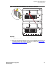
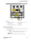
Cross-connect the cabinet to the patch panels
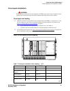
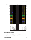
1 Cross-connect the port circuit packs to the G600 patch panels (or other standard 110A cross-
connect equipment). See Figure 19, Example cross-connect field’s patch-panel connections,
on
page 93.
Allowed circuit packs
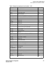
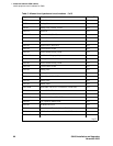
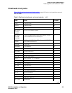
Table 5, Allowed circuit packs and circuit modules, on page 86 lists the circuit packs that can be used
with G600. (Table 6, Disallowed circuit packs and circuit modules,
on page 89 lists the circuit packs that
cannot be used with G600.)
Table 5: Allowed circuit packs and circuit modules 1 of 3
Apparatus code Name Allowed?
650A AC power unit Yes
NAA1 Fiber-Optic Cable Adapter circuit pack Yes
TN417 Auxiliary Trunk Yes
TN429/B/C/D Analog Direct Inward/Outward Dialing (DIOD) Central
Office Trunk
Yes
TN429C Analog Central Office Trunk Yes
TN429D Analog DIOD Trunk – Analog Loop Start Yes
TN433 Speech Synthesizer Yes
TN436B Direct Inward Dialing Trunk Yes
TN437B Tie Trunk Australia (future availability) Yes
1 of 3