


1 Install and cable a G600 cabinet
Connect modem to telephone network
134 S8100 Installation and Upgrades
November 2003
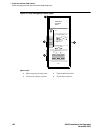
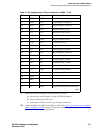
Trunk/auxiliary field: telephone used for emergency transfer and as normal extension
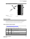
1 Connect a pair of wires between the -48V and GRD terminals on the yellow emergency transfer
row/connecting block to the EM TRANS RELAY PWR terminal.
2 Connect CO trunk leads from the purple field to the TC terminals on the yellow emergency
transfer row/connecting block for each trunk.
3 Connect CO trunk leads from the green field to the TK terminals on the yellow emergency
transfer row/connecting block for each trunk.
4 Connect telephone leads from the purple analog line board row/ connecting block to the LC
terminals on the yellow emergency transfer row/connecting block for each telephone.
5 Connect ST leads on the yellow emergency transfer row/connecting block for each emergency
transfer telephone to the ST terminal appearance in the purple trunk/auxiliary field.
6 Connect the ST leads from the terminal in Step 5 to the assigned terminal in the blue or white
station distribution field.
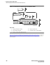
Telephone installation
1 Connect the telephone to the information outlet.
2 Install patch cords/jumper wires between the system side and the station side of the station
distribution field on the MDF.
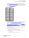
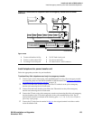
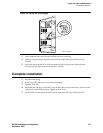
Connect modem to telephone network
1 Cross-connect the network jack on the modem to the network interface (via a 103A or modular
wall jack). See Table 22, Pinout of network jack,
on page 134 for the pinout.
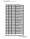
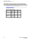
Table 22: Pinout of network jack
Pin number Signal
1Unused
2Tip
3Ring
4Unused